Al technical title is built by PatSnap Al team. It summarizes the technical point description of the patent document.
A plate-fin heat exchanger and brazing technology, which is applied in welding equipment, manufacturing tools, metal processing equipment, etc., can solve the problems of high temperature resistance, high pressure resistance, strength and service life, and reduce welding defects, Improve strength and plasticity, reduce material consumption
Active Publication Date: 2020-04-17
CHINA UNIV OF PETROLEUM (EAST CHINA)
View PDF7 Cites 0 Cited by
Summary
Abstract
Description
Claims
Application Information
AI Technical Summary
This helps you quickly interpret patents by identifying the three key elements:
Problems solved by technology
Method used
Benefits of technology
Problems solved by technology
[0004] For plate-fin heat exchangers serving at high temperatures, the conventional soldering or brazing methods can no longer meet the requirements of high temperature resistance, high pressure resistance, strength and service life.
Method used
Image
Click on the blue label to locate the original text in one second.
Reading with bidirectional positioning of images and text.
Examples
Embodiment Construction
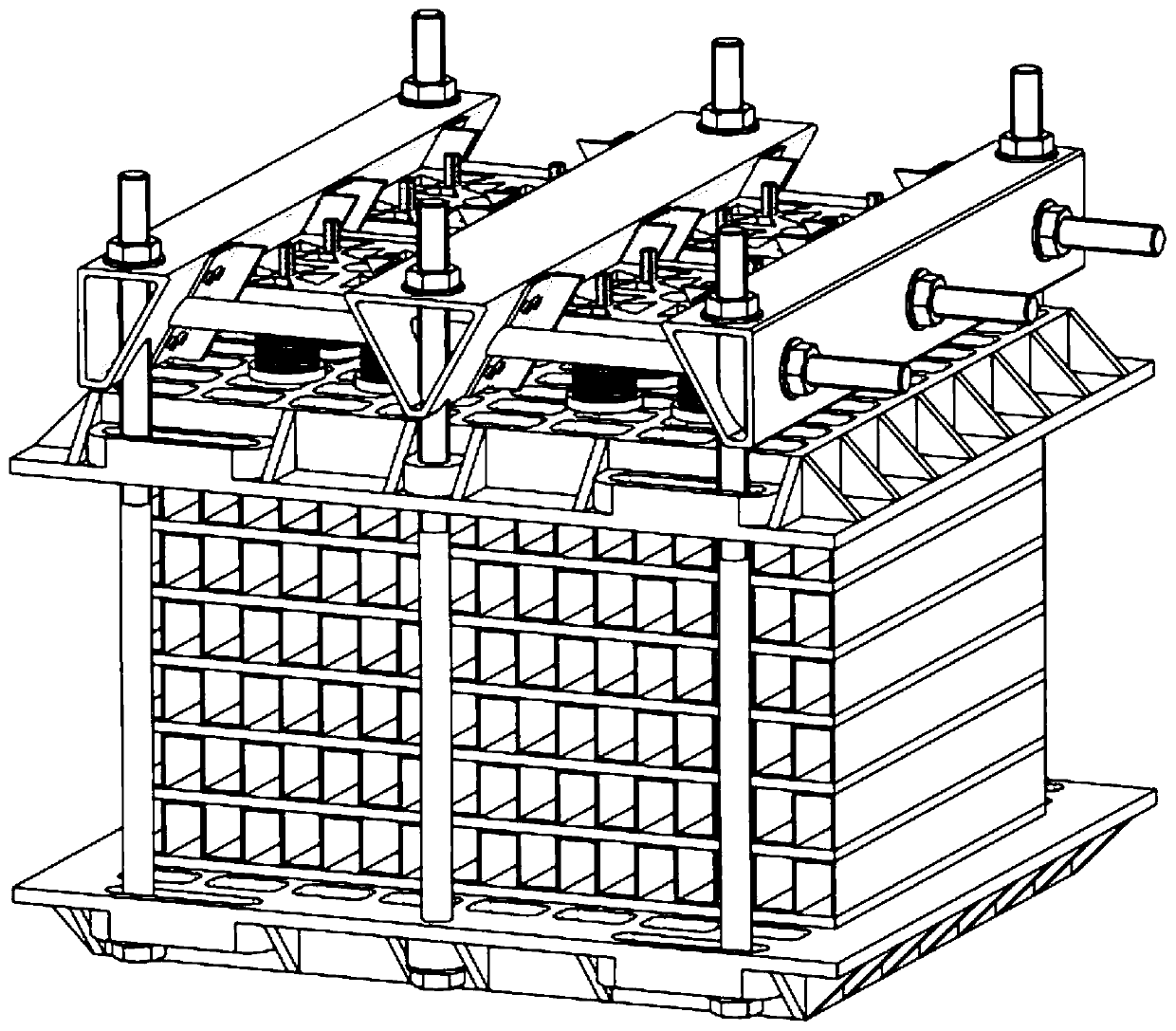
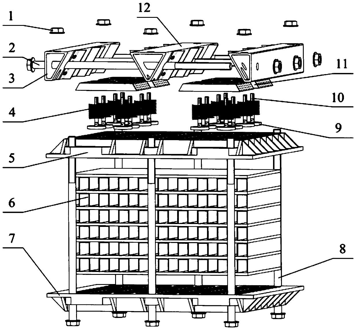
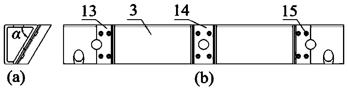
[0035] The present invention proposes a brazing fixture for a plate-fin heat exchanger, which consists of a nut 1, a top bolt 2, a side top bar 3, a spring 4, an upper cover plate 5, a lower bottom plate 7, a vertical bolt 8, a support plate 9, Measuring rod 10, pressing plate 11, middle top bar 12, side guide piece 13, middle guide piece 14, screw 15, spherical ball 16, bearing pin 17 form. A pressure plate 11 is placed between the side roof bar 3 and the middle roof bar 12, and a measuring rod 10 is interspersed on the pressure plate 11. The spring 4 is placed between the support plate 9 and the pressure plate 11, and the support plate 9 is placed on the upper cover plate 5. The plate-fin structure 6 is located between the upper cover plate 5 and the lower bottom plate 7 . The middle of the pressing plate 11, the upper cover plate 5 and the lower base plate 7 is a hollow structure, and between the side top bar 3 and the middle top bar 12, between each top bar and the lower b...
PUM
Abstract
The invention discloses a braze welding clamp of a plate-fin type heat exchanger. The clamp consists of a nut, a top bolt, a side top bar, a spring, an upper cover plate, a plate-fin structure, a lower bottom plate, a vertical bolt, a supporting plate, a measuring rod, a pressure plate, a middle top bar, a side guide sheet, a middle guide sheet, a bolt, a rolling ball and a pin, wherein the pressure plate is additionally arranged between the side top bar and the middle top bar; the measuring rod is inserted into the pressure plate in a through hole; the spring is placed between the supportingplate and the pressure plate; the supporting plate is placed on the upper cover plate; the plate-fin structure is positioned between the upper cover plate and the lower bottom plate; a part among thepressure plate, the upper cover plate and the lower bottom plate is of a hollow-out structure; the side top bar is assembled with the middle top bar through matching of a bolt and a nut; and each topbar is assembled with the lower bottom plate through matching of a bolt and a nut. The braze welding clamp can apply uniform pressure to the plate-fin structure in a vacuum braze welding process, so that distance among welding seams is reduced, a welding rate is increased, welding defects are reduced, and strength and plasticity of a braze welding joint are improved; and moreover, the clamp is high in heat transfer efficiency, is convenient in dismounting, and can shorten a braze welding period.
Description
technical field [0001] The invention relates to the field of welding processing tools, in particular to a brazing fixture for a plate-fin heat exchanger. Background technique [0002] Energy is the foundation and driving force of modernization, and energy supply and security are related to the overall situation of my country's modernization drive. At present, my country's demand for energy resources is increasing day by day, ecological and environmental problems are prominent, the pressure to adjust the structure, improve energy efficiency and ensure energy security is further increasing, and energy development is facing a series of new problems and challenges. In recent years, my country has proposed to develop modern industries that are low-carbon, environmentally friendly, energy-saving and emission-reducing. Improving energy utilization and reducing energy consumption have become the key to the development of modern industry. [0003] In high-energy industries such as ...
Claims
Application Information
Patent Timeline
Application Date:The date an application was filed.
Publication Date:The date a patent or application was officially published.
First Publication Date:The earliest publication date of a patent with the same application number.
Issue Date:Publication date of the patent grant document.
PCT Entry Date:The Entry date of PCT National Phase.
Estimated Expiry Date:The statutory expiry date of a patent right according to the Patent Law, and it is the longest term of protection that the patent right can achieve without the termination of the patent right due to other reasons(Term extension factor has been taken into account ).
Invalid Date:Actual expiry date is based on effective date or publication date of legal transaction data of invalid patent.