Cutting robot for aluminum alloy section and use method thereof

A technology for aluminum alloy profiles and cutting robots, which is applied to metal processing machinery parts, shearing devices, large fixed members, etc., can solve the problems of unsmooth cutting surface of aluminum alloy profiles, unstable cutting feed amount, and cumbersome processing operations. , to avoid secondary hair removal, improve cutting quality, and fix reliably and firmly

Inactive Publication Date: 2018-10-12
冯建利
View PDF0 Cites 4 Cited by
  • Summary
  • Abstract
  • Description
  • Claims
  • Application Information

AI Technical Summary

Problems solved by technology

[0005] Aiming at the deficiencies of the prior art, the present invention provides an aluminum alloy profile cutting robot and its use method, which solves the problem that the above-mentioned existing aluminum alloy profile cutting robots mostly use pneumatic or air push oil as the cutting power, compressed air or Hydraulic oil is used as the transmission medium, because both compressed air and hydraulic oil have compressibility, which makes the feeding process and cutting feed amount unstable, causing serious damage to the tool, and the cutting surface of the aluminum alloy profile is not smooth, and the cutting surface needs to be removed after cutting The burr operation makes the processing operation too cumbersome and the processing accuracy is too low

Method used


Image

  • Cutting robot for aluminum alloy section and use method thereof
  • Cutting robot for aluminum alloy section and use method thereof
  • Cutting robot for aluminum alloy section and use method thereof

Examples


Embodiment Construction

[0025] The following will clearly and completely describe the technical solutions in the embodiments of the present invention with reference to the accompanying drawings in the embodiments of the present invention. Obviously, the described embodiments are only some, not all, embodiments of the present invention. Based on the embodiments of the present invention, all other embodiments obtained by persons of ordinary skill in the art without making creative efforts belong to the protection scope of the present invention.

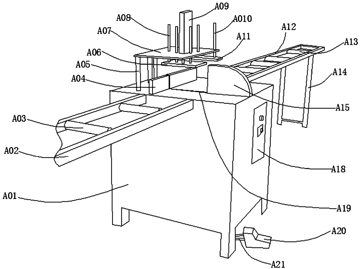
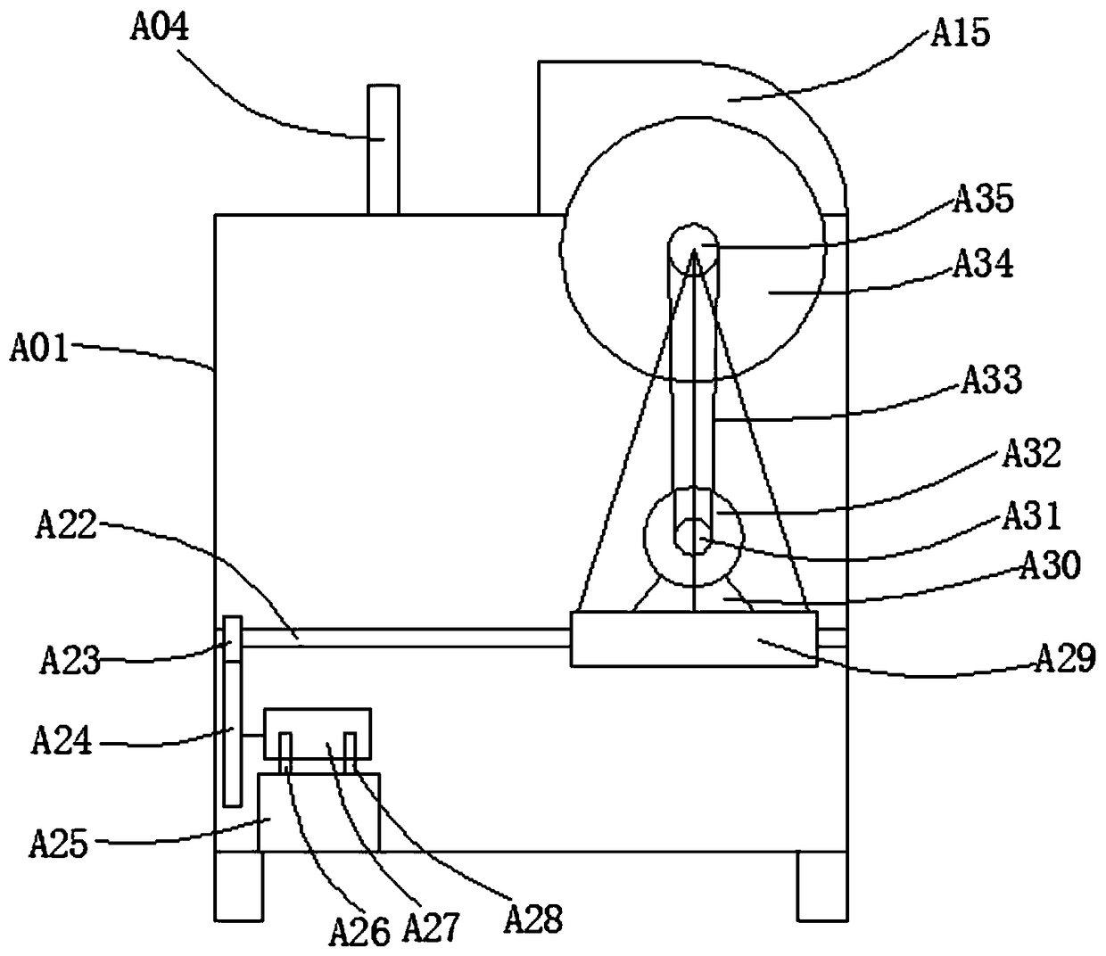
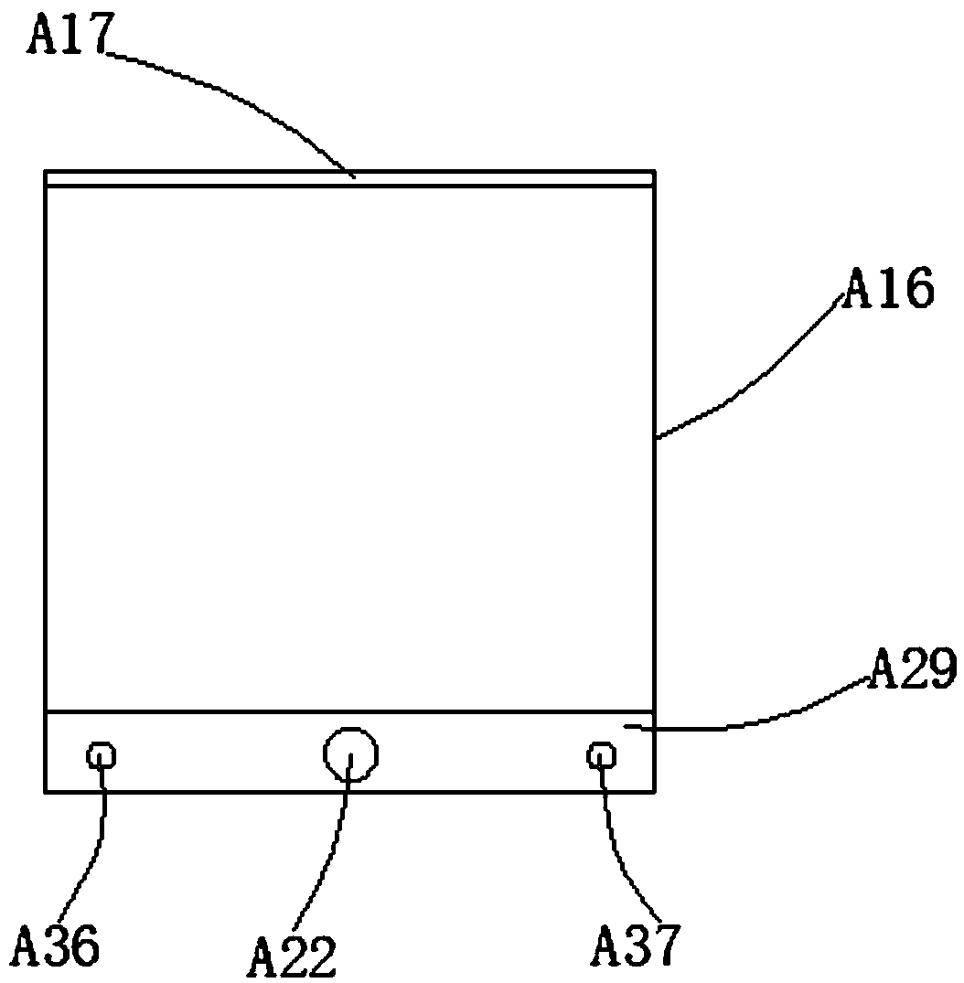
[0026] like Figure 1-Figure 3As shown, an aluminum alloy profile cutting robot includes a workbench A01, a support rod A05, and a bracket A25. The side of the workbench A01 is provided with a controller A18, and the bottom of the workbench A01 is provided with an air pipe A21. The end of the air pipe A21 is far away from the workbench A01. A foot pedal A20 is provided, a feeding frame A02 is provided on one side of the workbench A01, a support roller A03 is p...


PUM


Abstract

The invention provides a cutting robot for an aluminum alloy section and a use method thereof. The cutting robot for the aluminum alloy section comprises a working platform, a supporting rod and a second support, wherein a controller is arranged on the side surface of the working platform; an air pipe is arranged at the bottom part of the working platform, and a pedal plate is arranged at one end,far away from the working platform, of the air pipe; a feeding frame is arranged at one side of the working platform; a first supporting roller is arranged in the middle part of the feeding frame; adischarging frame is arranged at one side, far away from the feeding frame, of the working platform; and a second supporting roller is arranged in the middle part of the discharging frame. According to the cutting robot for the aluminum alloy section, the feeding frame is arranged, the aluminum alloy section is horizontally paved on the feeding frame and then pushed to the upper surface of the working platform; the aluminum alloy section is kept on one plane during the whole cutting process, so that the problem that the aluminum alloy section drops in cutting due to excessively high length, resulting in processing size deviation, can be avoided; and the aluminum alloy cutting accuracy can be improved.

Description

technical field [0001] The invention relates to the technical field of aluminum alloy profile processing, in particular to an aluminum alloy profile cutting robot and a use method thereof. Background technique [0002] Aluminum alloy profiles are the most widely used non-ferrous metal structural materials in the industry, and have been widely used in aviation, aerospace, automobiles, machinery manufacturing, ships, construction, decoration, and chemical industries. Most of the aluminum alloy profiles are long, and when they are cut during the processing and production process, it is easy to produce large dimensional processing deviations. Commonly used metal cutting machines cannot meet the technical requirements for precision machining of aluminum alloy profiles. The aluminum alloy cutting machine is a new product that replaces the old-fashioned profile cutting machine. The aluminum alloy cutting machine is characterized by fast speed, 5 times that of the old-fashioned pro...

Claims


Application Information

Patent Timeline
Patent Type & Authority Applications(China)
IPC IPC(8): B23D19/00B23D33/02B23D33/10B21D43/28B23Q1/25B23Q11/06B23Q11/08
CPCB23D19/00B21D43/28B23D33/02B23D33/10B23Q1/25B23Q11/06B23Q11/08
Inventor 冯建利
Owner 冯建利
Why Eureka
Try Eureka