
A method and system for controlling a brake lever

A technology for controlling brakes and brake levers, applied in the field of transportation, can solve problems such as hitting the brake levers, and achieve the effect of reducing the possibility

Active Publication Date: 2021-04-27
HANGZHOU HIKVISION DIGITAL TECH
View PDF9 Cites 0 Cited by
  • Summary
  • Abstract
  • Description
  • Claims
  • Application Information

AI Technical Summary

Problems solved by technology

[0005] In order to solve the problem that the vehicle is hit by the brake lever, the embodiment of the present invention provides a method and system for controlling the brake lever

Method used


Image

  • A method and system for controlling a brake lever
  • A method and system for controlling a brake lever
  • A method and system for controlling a brake lever

Examples


Embodiment Construction

[0066] In order to make the object, technical solution and advantages of the present invention clearer, the implementation manner of the present invention will be further described in detail below in conjunction with the accompanying drawings.

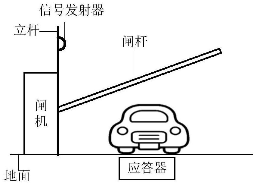
[0067] An embodiment of the present invention provides a method for controlling a brake lever, which can be applied to a barrier gate system. Among them, such as figure 1 As shown, the barrier gate system includes a signal transmitter, a transponder, a pole, a gate machine and a gate pole. The gate pole is installed on the control shaft of the gate machine. The gate machine can be used to control the fall or lift of the gate pole. The pole can be Set at the gate, for example, the pole can be set at the position where the symmetry axis of the plane intersecting the gate and the gate pole is located, the pole can be set on the top of the gate, and the pole can be set in the gate perpendicular to the ground At the position where the edge...


PUM


Abstract

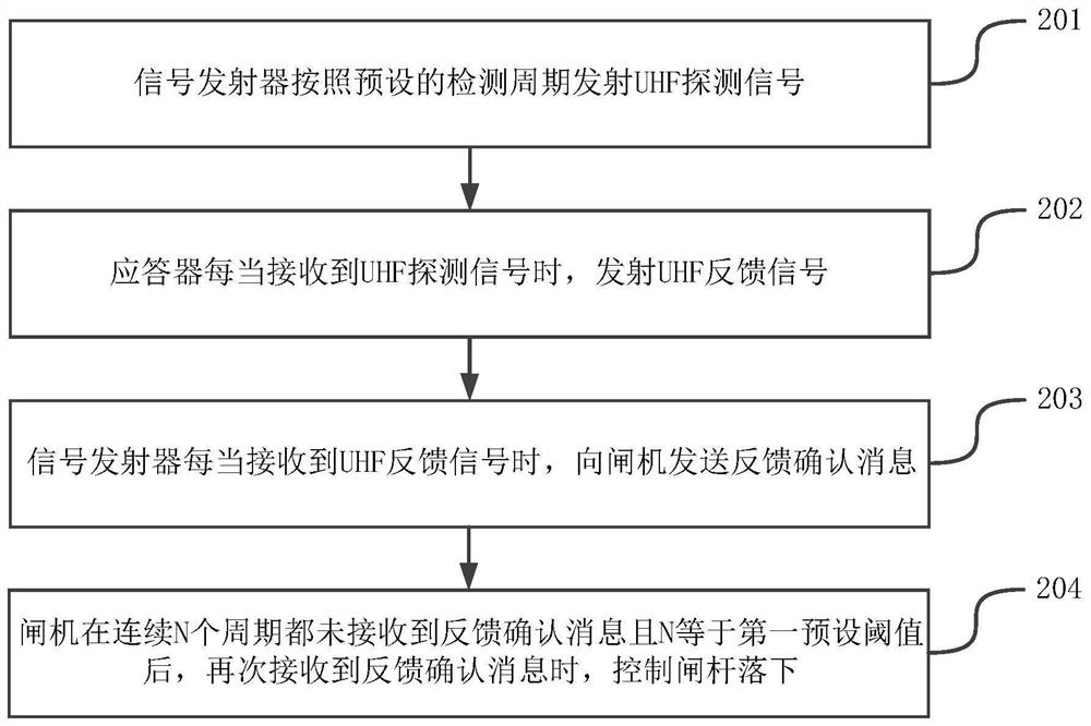
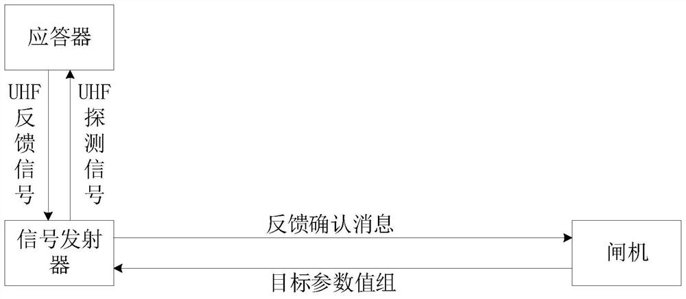
The invention provides a method and system for controlling a brake lever, belonging to the field of transportation. The method is applied to a barrier gate system, and the barrier gate system includes a signal transmitter, a transponder, a pole, a gate machine and a gate pole, the gate pole is installed on the control shaft of the gate machine, and the pole It is set at the gate, the signal transmitter is set on the pole, and the transponder is set on the ground directly below the gate bar. The method includes: the signal transmitter The detection cycle transmits a UHF detection signal; the transponder transmits a UHF feedback signal whenever it receives a UHF detection signal; the signal transmitter sends a feedback confirmation message to the gate whenever it receives a UHF feedback signal; After the gate does not receive a feedback confirmation message for N consecutive cycles and N is equal to the first preset threshold, when it receives a feedback confirmation message again, it controls the gate lever to drop. By adopting the invention, the possibility of the vehicle being hit by the brake lever can be reduced.

Description

technical field [0001] The invention relates to the field of transportation, in particular to a method and system for controlling a brake lever. Background technique [0002] Generally, the entrance and exit of the parking lot and the entrance and exit of the road toll station will be provided with barrier gates, which are used to charge vehicles for parking, etc., and the barrier gates include gate levers and gate machines. Take the user driving a vehicle into the parking lot as an example to illustrate the working principle of the barrier gate: when the user drives the vehicle past the entrance of the parking lot, the user can swipe the card, and the gate will detect the card swiping information, then record the vehicle, and control the brake lever to lift , the user drives the vehicle into the parking lot, and after the brake lever is lifted for a preset period of time, the gate machine controls the brake lever to fall. [0003] In the process of realizing the present in...

Claims


Application Information

Patent Timeline
Patent Type & Authority Patents(China)
IPC IPC(8): G07B15/04
CPCG07B15/04
Inventor 吴帅
Owner HANGZHOU HIKVISION DIGITAL TECH
Learn More