
Self-lubricating bearing pedestal

A technology of self-lubricating bearings and bearing housings, applied in bearings, bearing components, shafts and bearings, etc., can solve the problems of self-lubricating agents that cannot be evenly coated, and achieve the effects of avoiding outflow, reducing friction, and improving transmission efficiency

Inactive Publication Date: 2018-10-09
常州格兰芬医疗仪器有限公司
View PDF1 Cites 4 Cited by
  • Summary
  • Abstract
  • Description
  • Claims
  • Application Information

AI Technical Summary

Problems solved by technology

[0003] In order to overcome the deficiency that the existing self-lubricating agent cannot be evenly coated on the surface of the rotating shaft, the present invention provides a self-lubricating bearing seat, which solves the problem by filling lubricating oil inside the bearing pad and setting balls on the inner wall of the bearing pad

Method used


Image

  • Self-lubricating bearing pedestal
  • Self-lubricating bearing pedestal
  • Self-lubricating bearing pedestal

Examples


Embodiment Construction

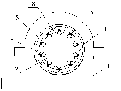
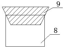
[0015] Such as figure 1 It is a structural schematic diagram of the present invention, a self-lubricating bearing housing, including a bearing housing main body 1 and a bearing bush 3 arranged in the central shaft hole 2 of the bearing housing main body 1, and a lubricating ring 4 filled with lubricating oil is arranged inside the bearing bush 3, and the lubricating ring 4. It communicates with the outside world through the ball 5 used for fluid conduction arranged on the inner wall of the bearing bush 3. The inner wall of the bearing bush 3 is provided with a notch for installing the ball 5. The notch communicates with the lubricating ring 4 through the corresponding oil delivery channel 7 to lubricate. The inner wall of the ring 4 is coated with protective paint. During installation and use, the upper and lower bearing seats are covered by bolts, and the bearing bush 3 is fixed in the central shaft hole. There is a lubricating ring 4 inside the bearing bush 3 for filling lub...


PUM


Abstract

The invention relates to the technical field of bearing pedestals, in particular to a self-lubricating bearing pedestal. The self-lubricating bearing pedestal comprises a bearing pedestal main body and a bearing bush arranged in a center axial hole of the bearing pedestal main body. A lubricating ring filled with lubricating oil is arranged inside the bearing bush. The lubricating ring communicates through the outside world through balls arranged on the inner wall of the bearing bush and used for guiding liquid. The inner wall of the bearing bush is provided with a notch for installation of the balls. The upper edge of the notch is provided with a bearing wall matched with the balls. The notch communicates with the lubricating ring through a corresponding oil conveying channel, the inner wall of the lubricating ring is coated with protection paint, the lubricating ring is provided with an oil injection hole, a sealing plug is arranged in the oil injection hole, traditional opening typeself-lubricating agent filling holes are replaced with the balls for guiding liquid, and lubricating agent is prevented from flowing out. Self lubrication for a rotating shaft is achieved through theballs making rolling contact with the outer surface of the rotating shaft, therefore, friction force between the rotating shaft and the bearing bush is reduced, and the transmission efficiency is improved during self lubricating.

Description

technical field [0001] The invention relates to the technical field of bearing seats, in particular to a self-lubricating bearing seat. Background technique [0002] The bearing seat is a large and extra-large bearing seat that can accept comprehensive loads and has a special structure. It has the characteristics of compact structure, sensitive rotation, and convenient maintenance of the device. Where there is a bearing, there must be a support point. The inner support point of the bearing is The shaft and the outer support are often referred to as bearing housings. The inner bearing bush and the rotating shaft in the existing bearing seat are prone to heat and wear due to rotation, so a lubricating oil outlet is added on the inner wall of the bearing bush. For example, the application number is CN201220287583.7, and the application date is June 19, 2012. Lubricated Sliding Bearing Housing" patent, the bearing housing through the self-lubricating agent filling hole filled w...

Claims


Application Information

Patent Timeline
Patent Type & Authority Applications(China)
IPC IPC(8): F16C35/02F16C33/04F16N1/00
CPCF16C35/02F16C33/04F16C2300/02F16N1/00F16N2210/14
Inventor 王岷颜
Owner 常州格兰芬医疗仪器有限公司
Learn More