
Rear wheel stabilizing device of bicycle

A stabilizer, bicycle technology, applied in chain/belt drive, vehicle parts, vehicle gearbox, etc., can solve the problems of poor body stability, difficulty in bicycles, many falls, etc., to achieve good stability, riding comfort, The effect of reducing bumps and vibrations

Pending Publication Date: 2018-10-09
HUZHOU VOCATIONAL TECH COLLEGE
View PDF0 Cites 0 Cited by
  • Summary
  • Abstract
  • Description
  • Claims
  • Application Information

AI Technical Summary

Problems solved by technology

Commonly seen bicycles on the market are two-wheeled devices, which tend to be unstable when driving, especially when the speed slows down, the bike will fall down uncontrollably
Also because of the poor stability, it is also very difficult when learning to ride a bicycle for the first time, and it is often necessary to fall a lot to learn
[0003] For example: the Chinese utility model that the patent No. is 012144711 discloses a kind of bicycle, comprises car faucet, front wheel and tripod, and frame rear portion is provided with flywheel, and the little fly coaxial with this flywheel, and there are big fly, small fly on the axle. There are big fly and small fly on the shaft. Wheels are installed at both ends of the shaft. The small fly and the front big fly are driven by a chain. The front big fly and the pedal are coaxial. The fly is driven by a chain, and the big fly is installed on the other side of the main shaft of the pedal. The small fly and the big fly are driven by a chain. The shaft is supported by a bearing, and the bearing seat is fixed on the rear frame. This bicycle adopts a Five wheels, but poor body stability when turning or driving on uneven roads, easy to roll over

Method used


Image

  • Rear wheel stabilizing device of bicycle
  • Rear wheel stabilizing device of bicycle
  • Rear wheel stabilizing device of bicycle

Examples


Embodiment

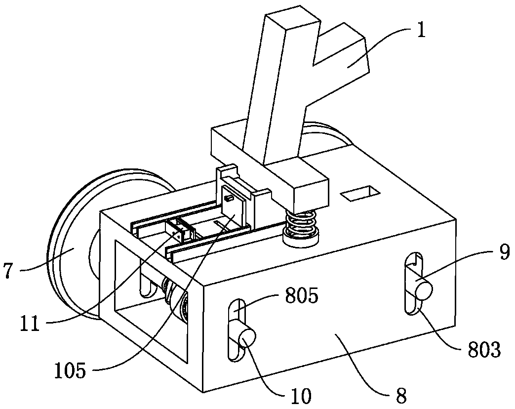
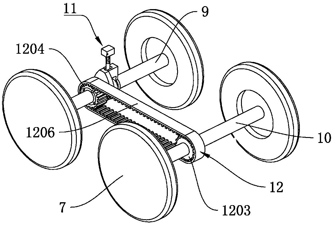
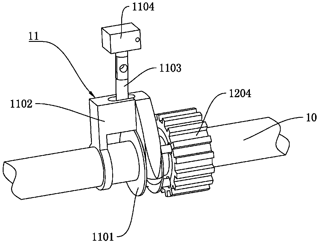
[0023] Example: such as Figure 1 to Figure 6 As shown, a rear wheel stabilizing device of a bicycle is used to be installed at the rear end position of the bicycle frame 1, and it includes a transmission box 8 installed at the rear end of the vehicle frame 1, a drive shaft 9 for installing the rear wheel 7 and a The driving shaft 10, the driving shaft 9 and the driven shaft 10 are arranged in parallel front and rear, a chain transmission mechanism is arranged between the driving shaft 9 and the driven shaft 10, and the driving shaft 9 drives the slave shaft through the chain transmission mechanism. The driving shaft 10 rotates synchronously, and the driven shaft 10 is provided with a clutch mechanism 11, and the clutch mechanism 11 controls the driven shaft 10 to rotate synchronously with the driving shaft 9 or to rotate independently.

[0024] Such as figure 1 , Figure 5 Figure 6 As shown, the transmission box 8 is provided with a long slot 803 arranged front and back, ...


PUM


Abstract

The invention relates to a rear wheel stabilizing device of a bicycle. The rear wheel stabilizing device comprises a transmission box, a driving shaft and a driven shaft for mounting the rear wheel, wherein the driving shaft and the driven shaft are arranged in parallel front and back; long grooves arranged in front and back are formed in the transmission box, and plungers moving up and down alongthe long grooves are arranged in the long grooves; the driving shaft and the driven shaft are correspondingly arranged on the plungers which correspond to each other in a front and back mode, and a hydraulic adjusting mechanism for driving the plungers to move up and down is arranged in the transmission box; a chain transmission mechanism is arranged between the driving shaft and the driven shaft, and the driving shaft drives the driven shaft to rotate synchronously through the chain transmission mechanism; and a clutch mechanism is arranged on the driven shaft, and the clutch mechanism controls the driven shaft and the driving shaft to rotate synchronously or rotate independently. According to the rear wheel stabilizing device, the stability and trafficability of a bicycle body are improved, and the bumping and vibration of a bicycle frame during traveling are reduced by hydraulic stress between axles and the transmission box, so that better stability is achieved on uneven roads, andthe rear wheel stabilizing device has the advantages of good stability, high passing capacity and comfortable riding.

Description

technical field [0001] The invention relates to the technical field of bicycles, in particular to a bicycle rear wheel stabilizer. Background technique [0002] Bicycle is a common travel tool in life. It has been nearly two hundred years since the bicycle was invented. People have carried out continuous transformation on bicycles and evolved to existing bicycles. The improvement of existing bicycles is generally based on the improvement of materials. In terms of application and power source, there are few improvements in the overall structure and stability of bicycles. Commonly seen bicycles on the market are two-wheeled devices, which tend to be unstable when driving, especially when the speed of the vehicle slows down, the bicycle will fall down uncontrollably. Also because of poor stability, it is also very difficult when learning to ride a bicycle for a beginner, and it often takes a lot of falls to learn. [0003] For example: the Chinese utility model that the paten...

Claims


Application Information

Patent Timeline
Patent Type & Authority Applications(China)
IPC IPC(8): B62M9/02
CPCB62M9/02
Inventor 戚榆迪周忠友
Owner HUZHOU VOCATIONAL TECH COLLEGE
Learn More