
Tool Fault Intelligent Diagnosis System

An intelligent diagnosis and fault technology, applied in the direction of manufacturing tools, wood processing appliances, circular saws, etc., can solve the problems of harsh noise, affecting production efficiency, cuts, etc., and achieve the effect of improving accuracy, simple structure and easy implementation.

Active Publication Date: 2020-04-21
天津盛聚达机械刀具有限公司
View PDF6 Cites 0 Cited by
  • Summary
  • Abstract
  • Description
  • Claims
  • Application Information

AI Technical Summary

Problems solved by technology

[0002] The tool is a tool used for cutting in mechanical manufacturing, but long-term use of the tool will cause blade wear, and the degree of tool wear directly affects the accuracy of the machined parts. When the tool wear is serious, the continued use of the tool will cause inaccurate processing of the workpiece, resulting in the scrapping of the workpiece. Make the machine tool vibrate, harsh noise or be forced to stop, and even cause the operation failure of the entire processing system, bringing safety hazards and economic losses. Therefore, the fault diagnosis of the tool is an inevitable task to ensure the normal operation of the machine tool
[0003] At present, tool fault diagnosis is mainly to observe with the naked eye by removing the tool regularly, and judge whether the tool is seriously worn according to the shape of the tool and the experience of the operator. Such tool fault diagnosis is not intelligent and requires a lot of labor costs. If tool diagnosis is performed frequently, it will also affect production efficiency and consume economic costs
Moreover, when performing fault diagnosis on a circular saw, since the circular saw is bulky and there are many saw blades in the circumferential direction of the circular saw, it is extremely inconvenient to manually remove the circular saw for visual observation. Yes, when the circular saw is removed, it is also easy to cause personal cuts
In addition, during the processing of the workpiece by the circular saw, slag will be generated, and the slag will stick to the saw blade and the workpiece. When the saw blade is stuck with too much slag, it will not be able to wear or break the saw blade. accurate detection of the situation

Method used


Image

  • Tool Fault Intelligent Diagnosis System
  • Tool Fault Intelligent Diagnosis System

Examples


Embodiment Construction

[0021] The following is a further detailed description through specific implementations:

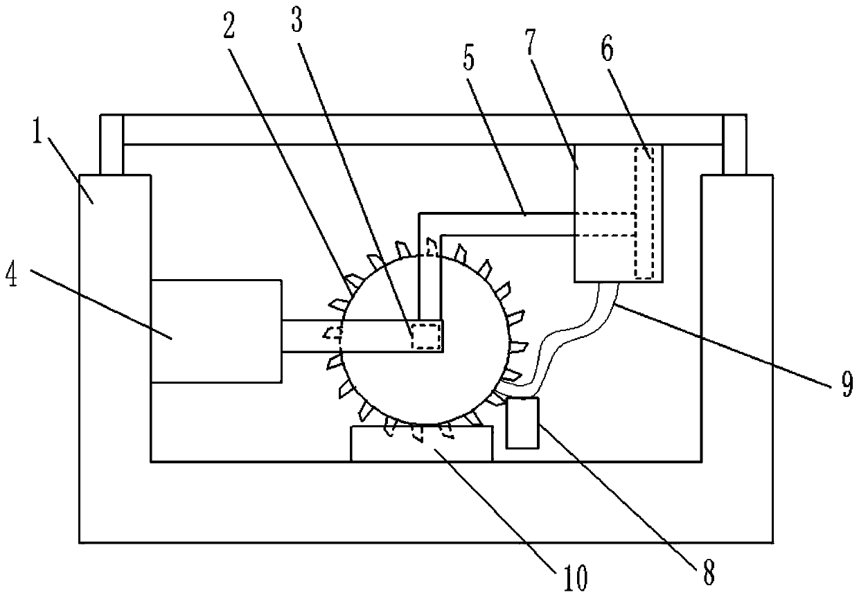
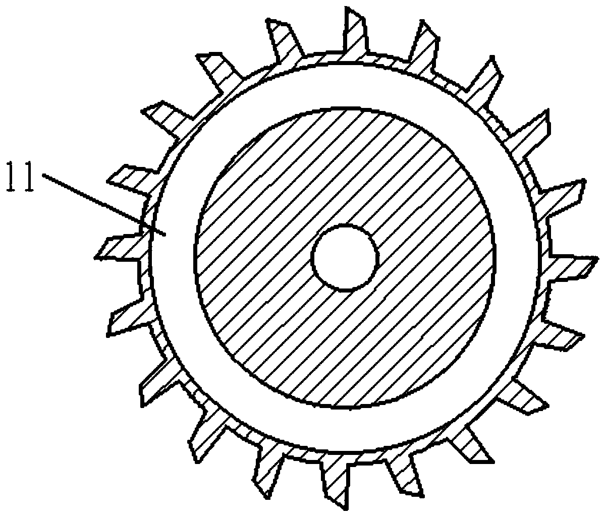
[0022] The reference signs in the drawings of the specification include: processing table 1, circular saw 2, connecting seat 3, cylinder 4, connecting rod 5, piston 6, air storage box 7, chip storage box 8, bellows 9, infrared receiver 10. Cavity 11.

[0023] The embodiment is basically as attached figure 1 Shown: The tool fault intelligent diagnosis system includes the processing table 1, the circular saw 2 and the power unit. The power unit includes the cylinder 4, the connecting seat 3 and the connecting column (not shown in the figure). The connecting seat 3 is welded to the cylinder 4 On the side of the piston rod, the end face of the connecting seat 3 is flat. The center of the circular saw 2 is provided with a through hole. The through hole is in interference fit with the connecting column. The connecting seat 3 and the corresponding position of the connecting column are provided with ...


PUM


Abstract

The invention relates to the technical field of cutting processing fault diagnosis, specifically to a tool fault intelligent diagnosing system. The tool fault intelligent diagnosing system comprises aprocessing table, a disc saw placed on the processing table and a power device which drives the disc saw to reciprocate horizontally, wherein the processing table is provided with an infrared detector for detecting damage of a saw web and an alarm device controlled by the infrared detector. The system also comprises a gas storage tank, wherein a piston is arranged in the gas storage tank, and thepiston is connected to the power device through a connecting rod; a gas inlet and a gas outlet are formed in the gas storage tank, and the gas outlet communicates to a corrugated pipe; a cavity is formed in the disc saw, a gas jet opening is formed in the peripheral surface of the disc saw, the cavity communicates to the corrugated pipe and the gas jet opening, separately, a chip storage tank isarranged on the corrugated pipe, the chip storage tank is close to the gas jet opening, and an opening is formed in the side, close to the gas jet opening, of the chip storage tank. The tool fault intelligent diagnosing system provided by the invention can diagnose faults of the disc saw accurately by cleaning the saw web.

Description

Technical field [0001] The invention relates to the technical field of cutting processing fault diagnosis, in particular to a tool fault intelligent diagnosis system. Background technique [0002] Cutting tools are used for cutting in mechanical manufacturing, but long-term use of the cutting tools will cause the cutting edge wear, and the degree of tool wear directly affects the accuracy of the processed parts. When the tool wear is severe, continued use will cause inaccurate processing of the workpiece and cause the workpiece to be scrapped. The machine tool produces vibration, harsh noise or forced shutdown, and even causes the operation of the entire processing system to malfunction, bringing safety hazards and economic losses. Therefore, fault diagnosis of the tool is an inevitable task to ensure the normal operation of the machine tool. [0003] At present, the tool fault diagnosis is mainly performed by unloading the tool on a regular basis to observe with the naked eye, and...

Claims


Application Information

Patent Timeline
Patent Type & Authority Patents(China)
IPC IPC(8): B27B5/00B27B5/29B27G19/02B27G3/00
CPCB27B5/00B27B5/29B27G3/00B27G19/02
Inventor 孙兵涛周余庆高晨雷芝
Owner 天津盛聚达机械刀具有限公司
Learn More