
Scintillation detection method with three-dimensional recognition distinguishing capability

A technology of scintillation detection and resolution capability, applied in the field of scintillation detection, can solve the problems of loss, increase the complexity of the detector system, and have no effective depth resolution capability, and achieve good energy resolution and time resolution.

Inactive Publication Date: 2018-10-02
INST OF HIGH ENERGY PHYSICS CHINESE ACADEMY OF SCI
View PDF8 Cites 4 Cited by
  • Summary
  • Abstract
  • Description
  • Claims
  • Application Information

AI Technical Summary

Problems solved by technology

[0007] 3) The system structure is complex
For large devices such as PET, the double-ended readout in the limited detector space increases the complexity of the detector system. At the same time, the complexity of the electronic system is also increased due to the doubling of the electronic signal volume processed, which also affects the The heat dissipation system puts forward higher requirements
[0008] In the method of single-ended readout, the method of cutting the scintillator bar into multiple segments can easily realize the resolution of the depth of action, but the scintillation light of the scintillator segment far away from the photodetector is in the process of propagating into the photodetector. There will be a large loss in the detector, which will affect the energy resolution and time resolution of the detector. This is a disadvantageous factor for some equipment that requires better energy resolution and time resolution, such as PET.
The remaining single-ended readout methods require pixel readout of the signal from the photodetector device, and the backend requires powerful electronic processing capabilities.
[0009] For all of the above reasons, there is currently no commercially available PET device with depth-of-action resolution for sale.

Method used


Image

  • Scintillation detection method with three-dimensional recognition distinguishing capability
  • Scintillation detection method with three-dimensional recognition distinguishing capability
  • Scintillation detection method with three-dimensional recognition distinguishing capability

Examples


Embodiment Construction

[0023] In the following specific implementation examples, the present invention will be further described in detail in conjunction with the accompanying drawings. These implementation examples are described in sufficient detail to enable those skilled in the art to practice the invention. Logical, implementation and other changes may be made in the implementation without departing from the spirit and scope of the invention. Therefore, the following detailed description should not be taken in a limiting sense, and the scope of the present invention is defined by the claims.

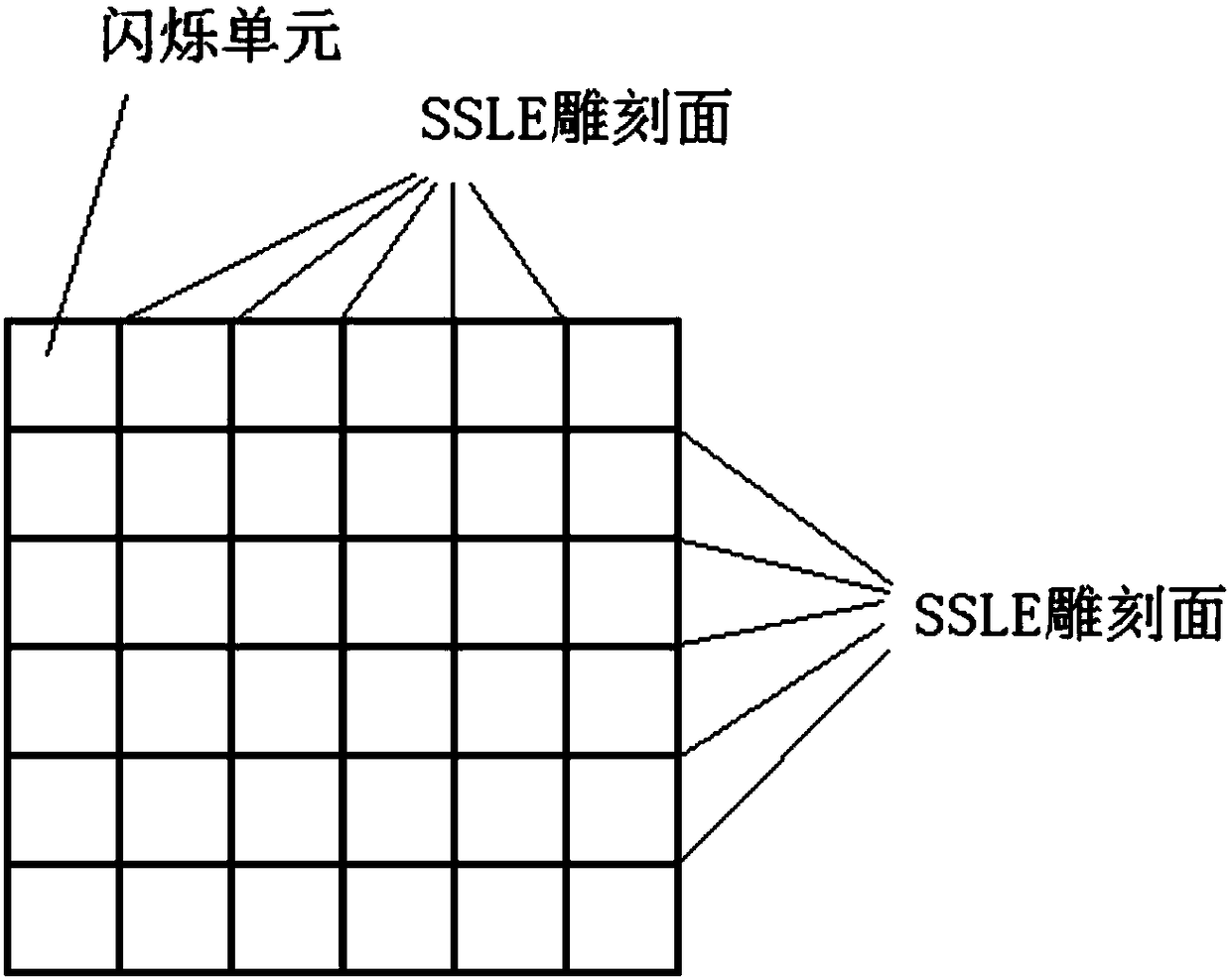
[0024] The present invention uses laser engraving technology to engrave a reflective surface in the whole scintillator to form a scintillator array, such as figure 1 As shown, the engraving surface of the laser engraving divides the whole scintillator into an array composed of multiple scintillating units; since the reflective surface formed by the laser engraving is composed of many micro-burst points, t...


PUM


Abstract

The invention discloses a scintillation detection method with the three-dimensional recognition distinguishing capability. The method comprises the steps: performing the calibration of instances at different depths in each scintillation unit of a scintillation detecting device through employing a radioactive source, and carrying out the fitting of a function of the action depth with respect to coordinates X, Y; solving the X and Y coordinates of any unknown instance detected by the scintillation detecting device through a centroid method, judging the number ij of the scintillation unit according to the range of the X and Y coordinates of the instance, selecting a corresponding function through the number ij of the scintillation unit, solving the maximum probability value of the depth of the instance, and taking the depth corresponding to the maximum probability value as the third-dimensional coordinate information of the occurrence position of the instance, wherein each scintillation unit is provided with a reflecting surface, and each reflecting surface is formed by the arrangement of a plurality of miniature burst points formed by laser inter-engraving. The method can be used forobtaining the information of the action depth, and is good in energy resolution and time resolution.

Description

technical field [0001] The invention belongs to the technical field of nuclear radiation detectors, and in particular relates to a scintillation detection method with three-dimensional position resolution capability. Background technique [0002] In the field of γ-ray detection, scintillation detector is a commonly used detector. It has the advantages of high gamma-ray detection efficiency, easy to make a larger sensitive volume, and strong adaptability to the environment. It is the best choice for detecting medium and high-energy gamma-rays. In many fields, it is necessary to judge the incident position of gamma rays, such as gamma camera, positron emission tomography (Positron Emission Tomography, PET), Compton camera and so on. Usually, scintillators need to be cut into strips to form arrays, and then coupled with position-sensitive photodetectors or photodetector arrays to obtain the ability to determine the position of incident γ-rays. However, this common position-se...

Claims


Application Information

Patent Timeline
Patent Type & Authority Applications(China)
IPC IPC(8): G01T1/20
CPCG01T1/20
Inventor 唐浩辉章志明王英杰李道武柴培韩笑柔魏龙
Owner INST OF HIGH ENERGY PHYSICS CHINESE ACADEMY OF SCI
Learn More