


Quick Research
Generate reliable direction feasibility study reports for your R&D in just a few steps.

Technical Q&A
Discover and master advanced knowledge NOW. Basics, ideas, possibilities, all at once.

Find Solutions
As an expert in R&D theories, this can generate solutions to your technical problems instantly.

Evaluate Feasibility
Analyze your overall solution with one click, know your potential R&D risks in advance.

Monitor Landscape
Get weekly tech updates, stay abreast of the latest tech innovations and key insights.
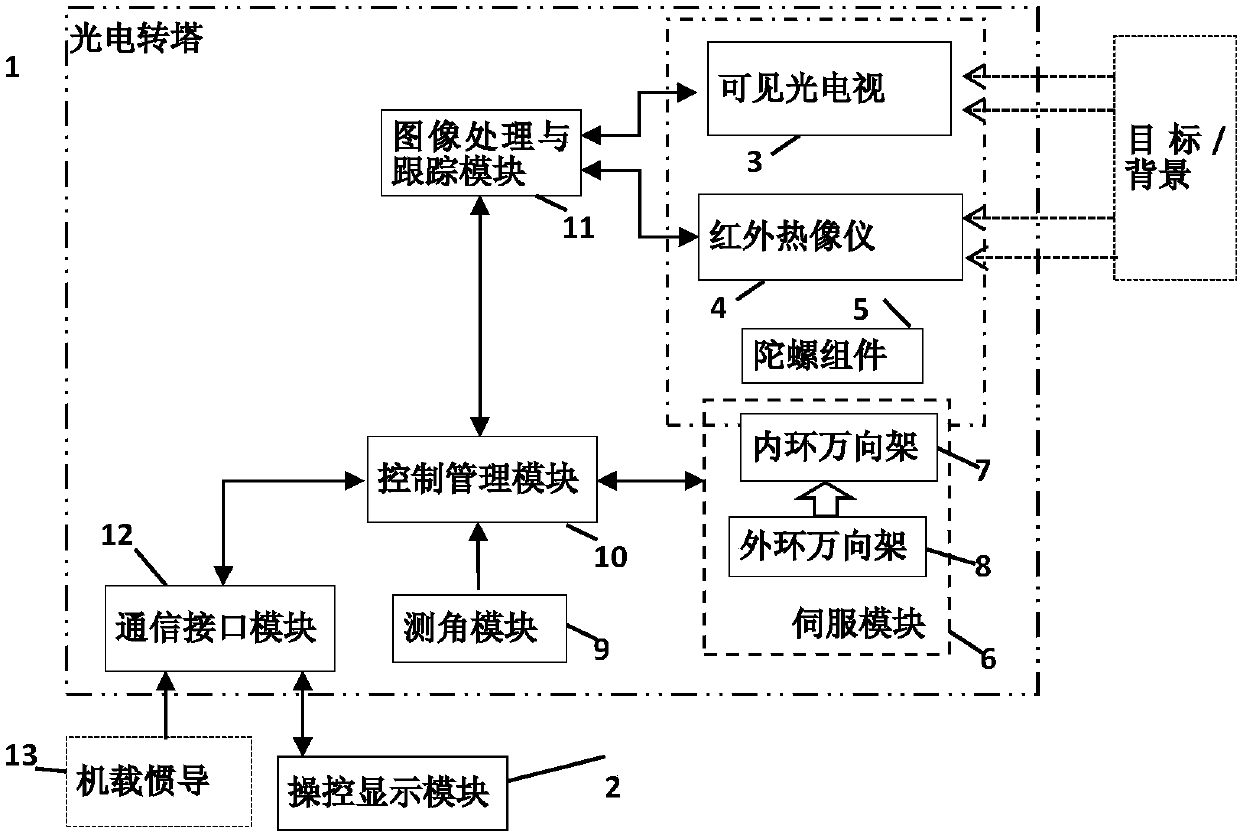
Airborne dual-band photoelectric wide-area reconnaissance and tracking device and method
A tracking device and dual-band technology, applied in the field of airborne dual-band optoelectronic wide-area reconnaissance and tracking devices, can solve the problems of high cost, constant change, large volume and weight, etc., and achieve the effect of improving the use efficiency of the equipment
- Summary
- Abstract
- Description
- Claims
- Application Information
AI Technical Summary
Problems solved by technology
Method used
Image

Examples
example
[0150] Flying altitude H: 5km, slant distance R=15km, aircraft flying speed V=180km / h=50m / s. Suppose the scanning speed is 30° / s, and the scanning range: ±ψ=±80°, therefore, t=160° / 30° / s=5.33s, so:
[0151]
[0152] If the slope distance R=30km, then the resolution change at this time is:
[0153]
[0154] Therefore, the image resolution caused by the scanning mode of the photoelectric turret 1 is relatively small, which can be approximately regarded as near-constant resolution scanning.
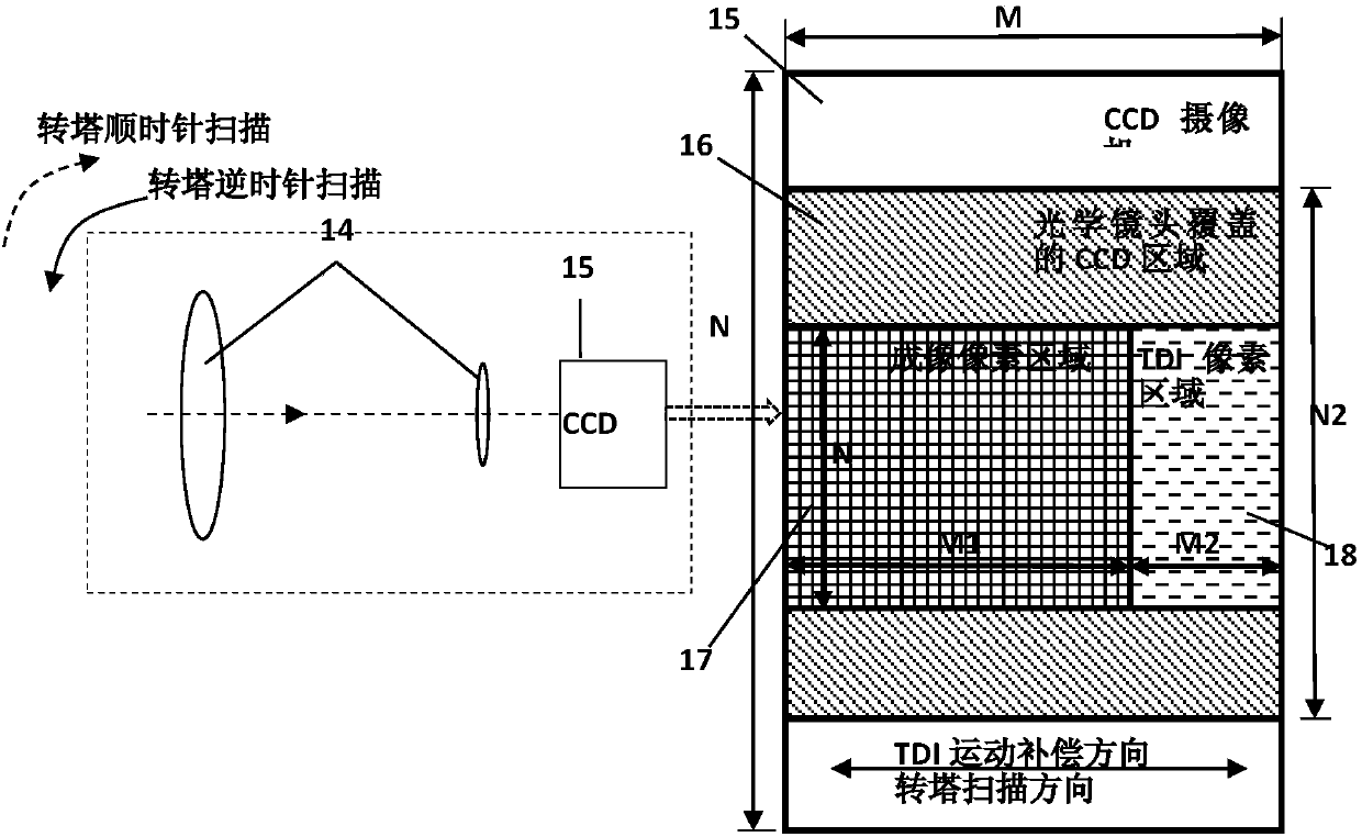
[0155] The motion compensation technology used in the existing system mainly only compensates the image blur caused by the forward motion of the aircraft and the left and right scanning motion perpendicular to the aircraft heading. The scanning direction is perpendicular to the aircraft heading, such as Figure 7 As shown, but the distance between each scanning area and the carrier aircraft changes greatly, resulting in a large change in the resolution of the scanned image obtained, w...
PUM
 Abstract
Description
Claims
Application Information
 - R&D Engineer
- R&D Manager
- IP Professional
- Industry Leading Data Capabilities
- Powerful AI technology
- Patent DNA Extraction
Browse by: Latest US Patents, China's latest patents, Technical Efficacy Thesaurus, Application Domain, Technology Topic, Popular Technical Reports.
© 2024 PatSnap. All rights reserved.Legal|Privacy policy|Modern Slavery Act Transparency Statement|Sitemap|About US| Contact US: help@patsnap.com