
Current sensor based on auto-bias magnetoelectric composite material

A magnetoelectric composite material and current sensor technology, applied in the direction of measuring current/voltage, instruments, measuring devices, etc., can solve the problems of complex sensor structure, unadjustable resonance frequency, unfavorable miniaturization, etc., and achieve small size, high sensitivity, Favorable effect of miniaturization

Inactive Publication Date: 2018-10-02
STATE GRID JIANGXI ELECTRIC POWER CO LTD RES INST +1
View PDF4 Cites 15 Cited by
  • Summary
  • Abstract
  • Description
  • Claims
  • Application Information

AI Technical Summary

Problems solved by technology

However, the current DC magnetic field of current sensors based on magnetoelectric composite materials is provided by permanent magnets, and the sensor structure is complex, difficult to install, not conducive to miniaturization, and the resonance frequency cannot be adjusted.

Method used


Image

  • Current sensor based on auto-bias magnetoelectric composite material
  • Current sensor based on auto-bias magnetoelectric composite material

Examples


Embodiment Construction

[0020] The present invention will be further described below in conjunction with the accompanying drawings, wherein the same structures are named with the same names. In describing the present invention, it should be understood that the terms "upper", "lower", "front", "rear", "left", "right", "top", "bottom", "inner", " The orientation or positional relationship indicated by "outside", etc. is based on the orientation or positional relationship shown in the drawings, and is only for the convenience of describing the present invention and simplifying the description, rather than indicating or implying that the referred device or element must have a specific orientation, so as to Specific orientation configurations and operations, therefore, are not to be construed as limitations on the invention.

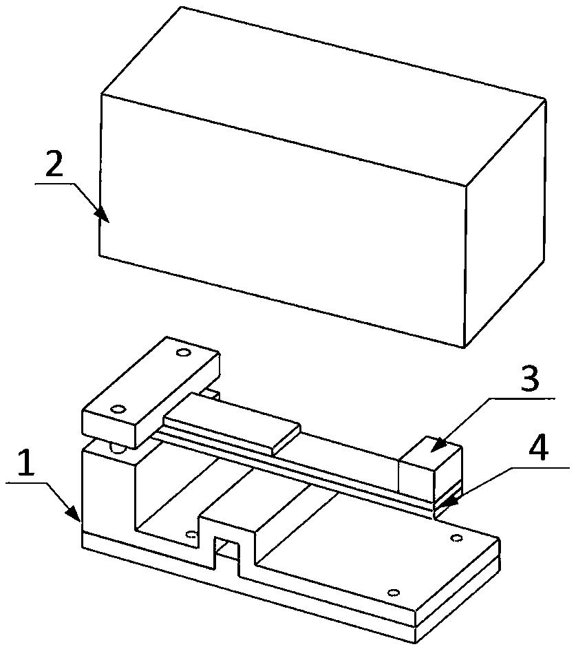
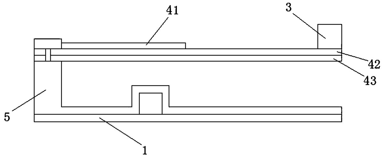
[0021] Such as figure 1 with figure 2 As shown, a current sensor based on a self-biased magnetoelectric composite material is composed of a support base 1, a packaging shell 2, a...


PUM


Abstract

The invention provides a current sensor based on an auto-bias magnetoelectric composite material; the current sensor comprises a support pedestal, a packaging housing, a mass block and an auto-bias magnetoelectric composite material; one end of the auto-bias magnetoelectric composite material is fixedly connected with the support pedestal, and the other end is connected with the mass block; the auto-bias magnetoelectric composite material comprises a hard magnetic thin layer, a magnetic induced shrinkage or elongation material layer and a piezoelectric material layer; the hard magnetic thin layer and the piezoelectric material layer are respectively laminated on the top and bottom surfaces of the magnetic induced shrinkage or elongation material layer; the hard magnetic thin layer providesa DC bias magnetic field for the magnetic induced shrinkage or elongation material layer, thus allowing the magnetic induced shrinkage or elongation material layer to make reactions on an annular minimal magnetic field formed by a current carrying wire under a zero bias magnetic field, finally enabling the magnetic induced shrinkage or elongation material layer to realize an auto bias magnetic-mechanical-electric coupling effect. When the auto-bias magnetoelectric composite material senses the annular magnetic field formed by the current carrying wire, electric output can be formed by the auto-bias magnetoelectric coupling effect, thus finally realizing current sensing.

Description

technical field [0001] The invention belongs to the field of current sensors, in particular to a current sensor based on self-biased magnetoelectric composite materials. Background technique [0002] Current sensing technology can be divided into contact current sensing and non-contact current sensing. In the contact current measurement, the sensing element is interconnected with the transmission line or equipment, and the electrical isolation between the primary and secondary equipment is not realized, which is easy to cause harm to personal safety. [0003] Non-contact detection generally measures the current indirectly by detecting the magnetic field generated by the current. There are many types of magnetic current sensing elements, which are divided into current transformers, Rogowski coils, Hall effect, giant magnetoresistance, and magneto-optical effects according to the test principle. . Due to its working principle, the traditional electromagnetic induction curren...

Claims


Application Information

Patent Timeline
Patent Type & Authority Applications(China)
IPC IPC(8): G01R19/00
CPCG01R19/00
Inventor 杨爱超单鹏刘明鲁彩江
Owner STATE GRID JIANGXI ELECTRIC POWER CO LTD RES INST
Learn More