
Intelligent biological retention tank and construction method thereof

A bioretention and construction method technology, applied in botany equipment and methods, planting substrates, drainage structures, etc., can solve the problems of permeable surface layer blockage, lack of "storage and use" functions, lack of purification, storage, utilization, etc. , to achieve the effect of convenient construction and maintenance, reduced construction cost and short construction period

Pending Publication Date: 2018-10-02
XIAN TECH UNIV
View PDF0 Cites 6 Cited by
  • Summary
  • Abstract
  • Description
  • Claims
  • Application Information

AI Technical Summary

Problems solved by technology

Permeable pavement is mainly used for sidewalks and municipal roads with small loads. Rainwater infiltrates through the permeable surface layer to replenish groundwater. Its functions mainly include: infiltration, retention, and discharge, and lack of purification, storage, and utilization functions; in addition, Its permeable surface layer is easily clogged by suspended particles in runoff
[0004] However, traditional low-impact facilities in the form of bioretention zones, grass ditch, and sunken green space mainly include the functions of "seepage, stagnation, purification, and drainage" and lack the functions of "storage and use". It is also restricted by the site and topographical conditions

Method used


Image

  • Intelligent biological retention tank and construction method thereof
  • Intelligent biological retention tank and construction method thereof
  • Intelligent biological retention tank and construction method thereof

Examples


Embodiment Construction

[0038] In order to make the object, technical solution and advantages of the present invention clearer, the present invention will be further described in detail below in conjunction with the accompanying drawings and embodiments. It should be understood that the specific embodiments described here are only used to explain the present invention, not to limit the present invention.

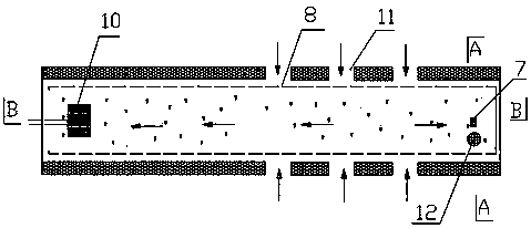
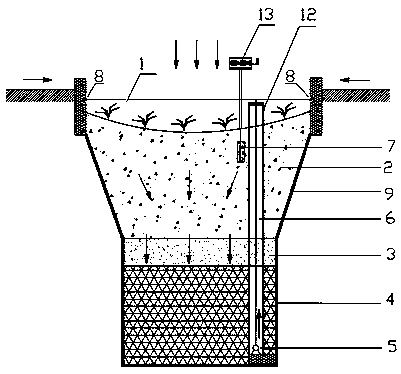
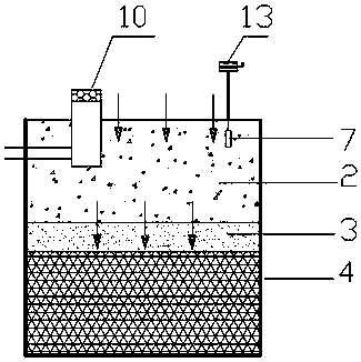
[0039] The present invention provides an intelligent bioretention tank (see figure 1 — Figure 4 ), there are inflow gaps 11 and perforated sprinkler pipes 8 on both sides of the retention tank. Including an automatic control system 13, the bottom of the water storage module layer 4 is provided with a recycling water pump 5 and an inspection well 12, the inspection well 12 extends out of the packing layer 2, and the inspection well 12 is provided with a refilling water distribution pipeline 6 , the backfilling water distribution pipeline 6 is connected to the recycling water pump 5, the surface l...


PUM


Abstract

The invention relates to the technical field of rainwater collection and purification of sponge cities, in particular to an intelligent biological retention tank and a construction method thereof. Theretention tank makes up for the shortage of the existing facilities to the back-use and self-control of rain water. According to the technical scheme: the two sides of the detention tank are providedwith an inflow notch and a perforated spray irrigation pipe along the stone, the retention groove comprises a surface water storage layer, a filling layer, a middle sand permeable layer and a water storage module layer from top to bottom, and also comprises an automatic control system, a back-use water pump and an inspection well are arranged at the bottom of the water storage module layer, a recharge water pipeline is arranged in the inspection well, the recharge water cloth pipeline is connected with the back-use water pump, the inspection well extends out of the filling layer, the surfacelayer of the filling layer is provided with a soil moisture sensor, an automatic control system is connected with the soil moisture sensor and the back-use water pump, the recharge water pipeline extends out of the filling layer and is connected with the perforated spray irrigation pipe, an overflow well is arranged in the filling layer, and the wellhead of the overflow well is higher than the surface of the filling layer. The retention tank is constructed by using a special method.

Description

technical field [0001] The invention relates to the technical field of rainwater collection and purification in a sponge city, in particular to an intelligent biological retention tank and a construction method thereof. Background technique [0002] With the rapid development of society and economy, urban water safety and water environment problems are becoming more and more serious, and more and more cities are frequently experiencing environmental problems such as heavy rain, internal waterlogging, and black and smelly water bodies. To this end, a new generation of urban stormwater management concept, namely sponge city, is proposed. Sponge city refers to strengthening urban planning and construction management, giving full play to the absorption, storage and slow release of rainwater by ecological systems such as buildings, roads, green spaces, and water systems, effectively controlling rainwater runoff, and realizing natural accumulation, natural infiltration, and natura...

Claims


Application Information

Patent Timeline
Patent Type & Authority Applications(China)
IPC IPC(8): E03F1/00E03F5/10E03F5/04A01G9/02A01G24/25A01G24/22A01G24/15A01G24/13A01G25/02
CPCA01G9/02A01G24/13A01G24/15A01G24/22A01G24/25A01G25/02E03F1/00E03F5/0401E03F5/10
Inventor 刘增超
Owner XIAN TECH UNIV
Learn More