
desalination

A compartmental, ion-based technology, applied in the field of desalination, which can solve the problems of large concentration differences, high water loss, high cost, etc.

Active Publication Date: 2021-07-16
FUJIFILM MFG EURO
View PDF7 Cites 0 Cited by
  • Summary
  • Abstract
  • Description
  • Claims
  • Application Information

AI Technical Summary

Problems solved by technology

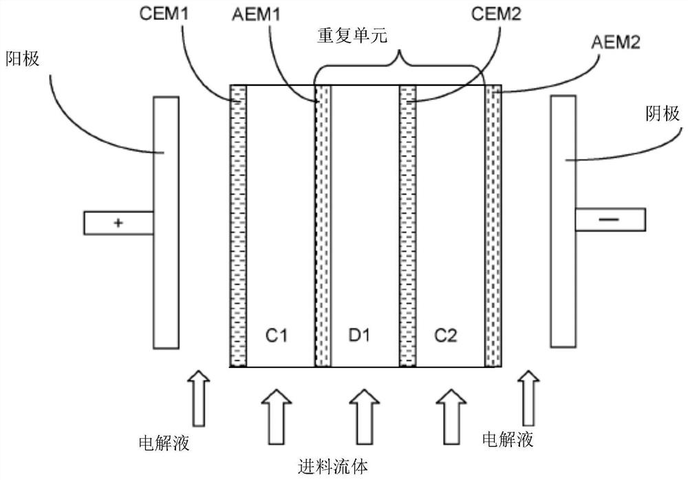
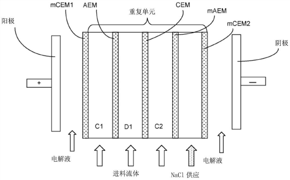
[0016] figure 2 A problem with the known ED units used in the EDM shown in is that it is difficult to produce drinking water from seawater at high yields due to the large concentration differences between the ion diluting and ion concentrating chambers
This results in high water loss due to osmotic transport of water molecules across the membrane wall from the ion diluting compartment to the ion concentrating compartment
figure 2 Another disadvantage of the known EDM unit shown is the need to supply sodium chloride solution (in the rightmost compartment), which leads to higher costs, not only concerning the required materials (ie sodium chloride) , but also involves additional energy due to the transport of sodium and chloride ions across the membrane wall
The requirement for a compartment dedicated to the supply of NaCl solution also reduces the desalination capacity of the EDM unit

Method used


Image

  • desalination
  • desalination
  • desalination

Examples


example 1

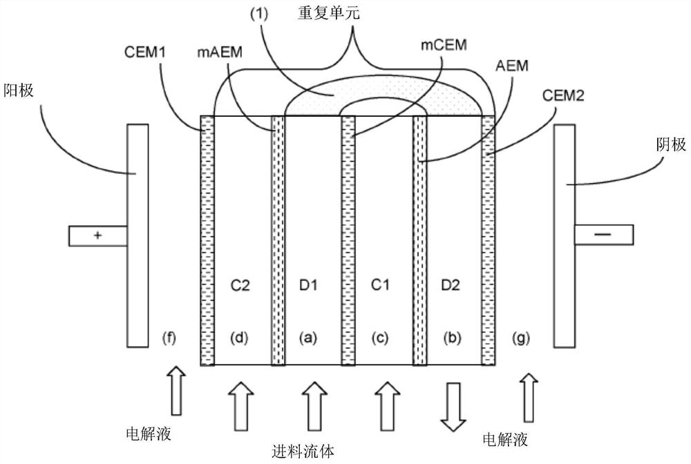
[0220] Membrane stack MS1 containing 81 membranes was constructed. The order of the membranes in the stack is [CEM-AEM-mCEM-mAEM-] n CEM, where n is 20. The membranes mCEM and mAEM are located on each side of compartment (a), and the membranes CEM and AEM within square brackets are located on each side of compartment (b). Thus, the stack comprises repeating units of compartments [(b), (c), (a), (d)] n .

[0221] The stack consisted of the membranes in the above sequence, a spacer between each membrane and the next (a 480 μm thick woven spacer from Deukum GmbH), one inlet for the feed liquid, two inlets for the concentrate , one outlet for the desalted liquid and two outlets for the concentrate and pipes fluidly connecting each compartment (a) with compartment (b).

[0222] In addition, the stack is configured such that fluid passing through compartment (a) flows in the opposite direction to fluid passing through compartment (b), and between fluids passing through compartme...

example 2

[0254] Similar simulation experiments were performed, but the flow between ED units was in a co-current direction. For these three steps, the same feed fluid requiring desalination and the same settings as in Example 1 were used. Therefore, the feed fluid that needs to be desalted is used as input to the ion diluting compartment (a) and concentrating compartments (c) and (d) of EDM1. Fluid flowing out of compartment (a) of EDM1 is also fed into compartment (b) of EDM1. The fluid flow was recirculated through compartments (a) and (b) of EDM1 until the conductivity of the fluid to be desalinated decreased to 27.1 mS / cm, while the fluid flow out of compartments (c) and (d) were respectively Recirculation back through compartments (c) and (d) of EDM1. The three fluid streams exiting compartments (b), (c) and (d) of EDM1 are respectively fed into compartments (a), (c) and (d) of EDM2 for the second step. In the second step, the fluid to be desalinated is recirculated through the...


PUM

PropertyMeasurementUnit
heightaaaaaaaaaa
areaaaaaaaaaaa
hardnessaaaaaaaaaa

Abstract

A membrane stack comprising the following components: (a) a first ion dilution chamber (D1); (b) a second ion dilution chamber (D2); (c) a first ion concentration chamber (C1); (d) a second ion dilution chamber (D2); Two ion concentration compartments (C2); and (e) membrane walls (CEM1, mAEM, mCEM, AEM, CEM2) between each compartment and on the outside of the first and last compartments of the stack, wherein: (i) Each membrane wall includes either a cation exchange membrane (CEM1, mCEM, CEM2) or an anion exchange membrane (mAEM, AEM), and the order of the cation exchange membranes and anion exchange membranes is alternate from each wall to the next; ( ii) the membrane walls (mAEM, mCEM) on each side of compartment (a) are more selective for monovalent ions than the corresponding membrane walls (AEM, CEM2) on each side of compartment (b); and (iii ) The stack further comprises means for transferring fluid between compartments (a) and (b).

Description

technical field [0001] The present invention relates to a membrane stack, an electrodialysis cell, an apparatus comprising at least two electrodialysis (ED) cells and a desalination method. Background technique [0002] The world's increasing population, diminishing water supplies, and droughts have led to increased demand for fresh water. A process known as electrodialysis ("ED") is known for converting saline water and providing drinking water. The method is especially useful in coastal areas where there is ample supply of salt water. The first commercial ED units were developed in the 1950s. Since then, improvements in ion-exchange membranes have led to significant advances in ED. [0003] An ED unit typically includes one or more membrane stacks. Each membrane stack includes an anode, a cathode, and a plurality of cell pairs through which a fluid passes. The cell pair includes an ion diluting chamber and an ion concentrating chamber. Each cell includes walls made o...

Claims


Application Information

Patent Timeline
Patent Type & Authority Patents(China)
IPC IPC(8): C02F1/469C02F1/46B01D61/44B01D61/58B01D61/50B01D63/08B01D69/06C02F103/08C02F1/52C02F1/44C02F1/42C02F1/28
CPCB01D61/44B01D63/082C02F1/04C02F1/283C02F1/42C02F1/441C02F1/442C02F1/444C02F1/447C02F1/4604C02F1/4691C02F1/4693C02F2001/5218C02F2103/08C02F2201/004C02F2201/007C02F2201/4611C02F2201/46115C02F2201/46135C02F2201/4614C02F2201/46145C02F2201/4618C02F2301/046C02F2301/08C02F2303/22Y02A20/131B01D61/50Y02A20/124B01D61/463B01D63/0822C02F2001/422C02F2001/425
Inventor 维诺德纳拉因·贝克亚茨科·赫辛
Owner FUJIFILM MFG EURO
Learn More