Direct-drive transmission mechanism

A transmission mechanism and direct drive technology, applied in the direction of electromechanical devices, structural connections, electric components, etc., can solve the problems of repeated positioning accuracy and poor positioning accuracy, large section width, cumulative error of mechanical parts, ball screw backlash error, etc. Achieve the effect of eliminating backlash error and reducing cost

Pending Publication Date: 2018-09-28
SUZHOU LINGHOU ROBOT
View PDF0 Cites 0 Cited by
  • Summary
  • Abstract
  • Description
  • Claims
  • Application Information

AI Technical Summary

Problems solved by technology

[0002] The traditional servo motor ball screw module has the cumulative error of each mechanical part and the backlash error of the reciprocating motion of the ball screw, so the repeat positioning accuracy and positioning accuracy are poor
In addition, the ball screw module is not suitable for multi-mover movement. Due to the limited processing technology of the ball screw, it is not suitable for the movement of ultra-long strokes, while the linear motor module can meet the needs of high-precision, high-speed, and ultra-long strokes. sports occasion
With the continuous development of technology, linear motor modules will definitely replace ball screw modules, but most linear motor modules have a large section width and occupy a large installation space, so they are not suitable for replacing KK modules.

Method used


Image

  • Direct-drive transmission mechanism
  • Direct-drive transmission mechanism
  • Direct-drive transmission mechanism

Examples


Embodiment 1

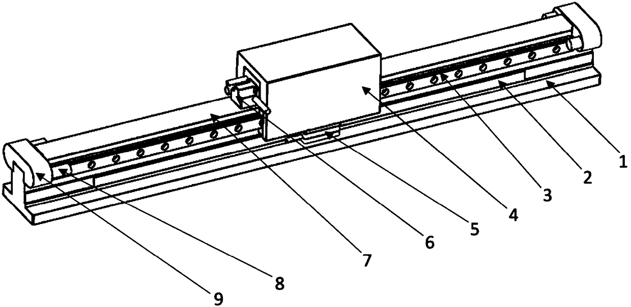
[0019] Such as figure 1 As shown, this embodiment includes a base 1, a guide rail 3 is provided on the top surface of the base 1, a slide seat 4 is provided on the guide rail 3 to move along the guide rail, the slide seat 4 is fixed with a mover coil assembly 6 by screws, and the base side is provided with The stator permanent magnet 7, the mover coil assembly 6 corresponds to the stator permanent magnet 7, and there is an air gap between the two. The non-contact transmission of the mover coil assembly 6 and the stator permanent magnet 7 can avoid mechanical wear and tear during movement. Backlash, high reliability, long life;

[0020] Corresponding to the guide rail 3, this embodiment is provided with a magnetic scale 2 parallel to it, and the slide 4 is provided with a reading head 5 corresponding to the magnetic scale 2, and real-time feedback is performed through the high-resolution position detection of the magnetic scale 2 and the reading head 5 , to achieve full closed...

Embodiment 2

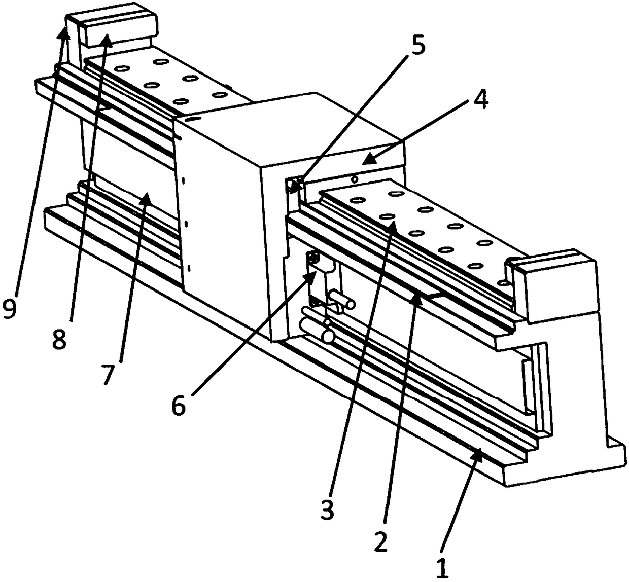
[0027] Such as figure 2 As shown, the difference between this embodiment and Embodiment 1 is that the guide rails 3 are double row guide rails, which are arranged on both sides of the base 1, one of the guide rails 3 is paired with a magnetic scale 2, and the slide seat 4 adopts U-shaped structure, the mover coil assembly 6 is directly potted in the sliding seat 4, the stator permanent magnet 7 is arranged on the top surface of the base 1, the mover coil assembly 6 and the stator permanent magnet 7 are placed in parallel, and an air gap is ensured. The positions of the limit block 8, the hard limit seat 9 and the reading head 5 change accordingly.

[0028] The double-row guide rails have a symmetrical structure, have higher rigidity, and can bear larger loads.

Embodiment 3

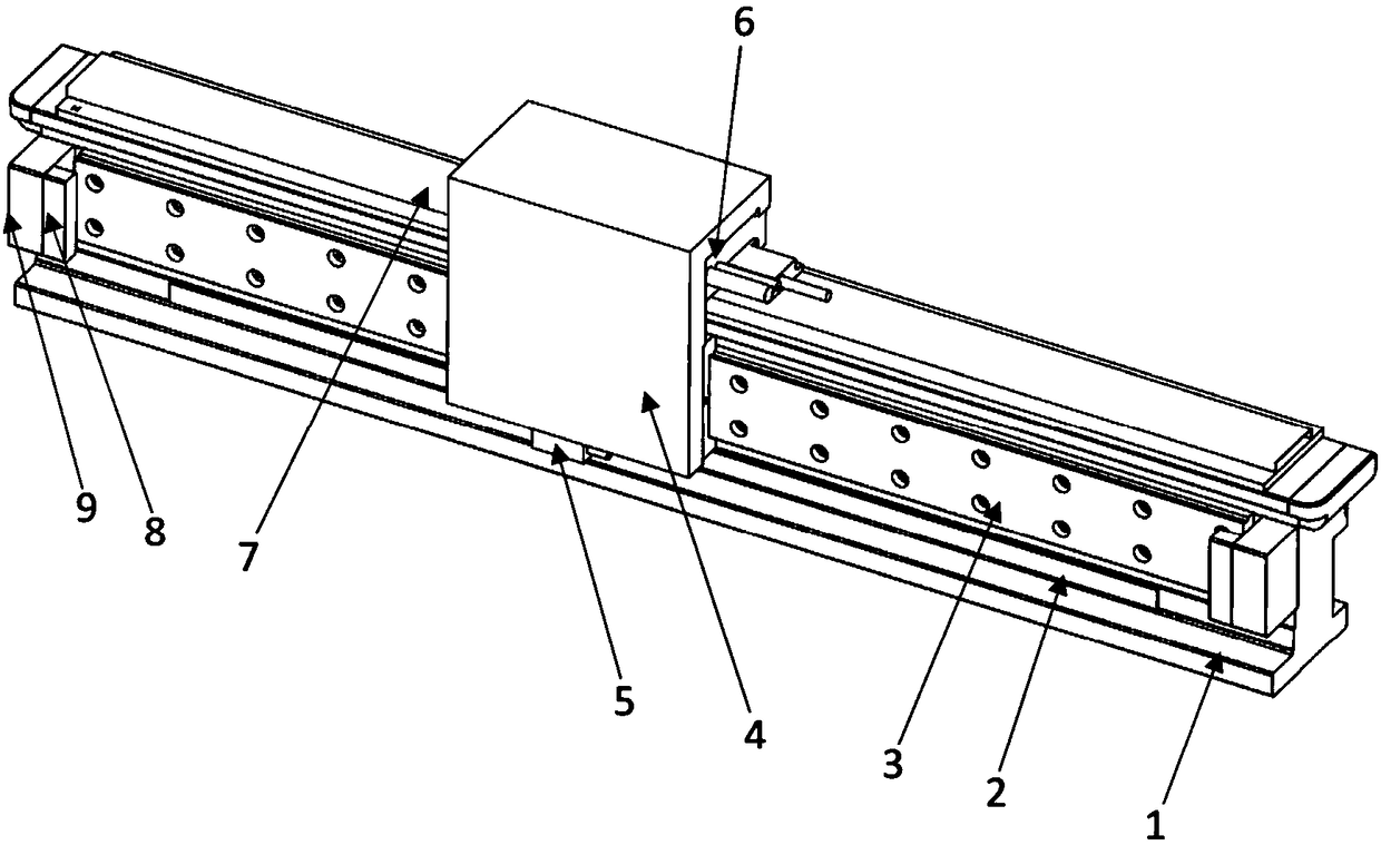
[0030] Such as image 3 As shown, the difference between this embodiment and Embodiment 1 is that the guide rail 3 and the magnetic scale 2 are arranged on one side of the base 1, the stator permanent magnet 7 is arranged on the top surface of the base 1, and the mover coil assembly 6 is set on the corresponding installation surface of the sliding seat 4, placed parallel to the stator permanent magnet 7, and ensures the air gap. The positions of the limit block 8, the hard limit seat 9 and the reading head 5 change accordingly.


PUM


Abstract

The invention discloses a direct-drive transmission mechanism in the technical field of linear motors. The direct-drive transmission mechanism comprises a base and a corresponding guide rail, whereina stator permanent magnet and the guide rail are arranged on the base, a sliding seat which moves along the guide rail is arranged on the guide rail, a rotor coil assembly is fixed on the sliding seat, and the stator permanent magnet and the rotor coil assembly correspond to each other and an air gap is formed between the stator permanent magnet and the rotor coil assembly; and the direct-drive transmission mechanism is provided with a magnetic railing ruler parallel to the direct-drive transmission mechanism, and the sliding seat is provided with a reading head corresponding to the magnetic railing ruler. The direct-drive transmission mechanism adopts a technology of direct driving by the linear motor, an accumulative error caused by more middle transmission parts and a back clearance error of the reciprocating motion of a ball screw of a traditional ball screw module of a servo motor are eliminated, the high-precision, high-speed and super-long-stroke movement can be achieved, and the reliability lifetime is long.

Description

technical field [0001] The invention relates to a technology in the field of linear motors, in particular to a direct drive transmission mechanism. Background technique [0002] The traditional servo motor ball screw module has the cumulative error of each mechanical part and the backlash error of the reciprocating motion of the ball screw, so the repeat positioning accuracy and positioning accuracy are poor. In addition, the ball screw module is not suitable for multi-mover movement. Due to the limited processing technology of the ball screw, it is not suitable for the movement of ultra-long strokes, while the linear motor module can meet the needs of high-precision, high-speed, and ultra-long strokes. sports occasions. With the continuous development of technology, linear motor modules will surely replace ball screw modules, but most linear motor modules have a large section width and occupy a large installation space, so they are not suitable for replacing KK modules. ...

Claims


Application Information

Patent Timeline
Patent Type & Authority Applications(China)
IPC IPC(8): H02K41/03H02K11/21
CPCH02K41/031H02K11/21
Inventor 孟健王波侍贤飞高尧檀俊阳刘树磊
Owner SUZHOU LINGHOU ROBOT
Why Eureka
Try Eureka