
a 3d printer

A 3D printer and print head technology, applied in 3D object support structures, additive manufacturing, coating devices, etc., can solve problems such as large vibration of the print head, vibration of printed objects, deformation of printed objects, etc., to achieve good load capacity and lighten The effect of increased print head weight and printing speed

Inactive Publication Date: 2018-04-13
徐开明 +3
View PDF5 Cites 0 Cited by
  • Summary
  • Abstract
  • Description
  • Claims
  • Application Information

AI Technical Summary

Problems solved by technology

Disadvantages: the installation process is more complicated and maintenance is more difficult; the cost of the whole machine is higher; the belt is easy to age, loosen and have empty return errors (prominent shortcomings)
Disadvantages: When printing, the printed object moves back and forth with the hot bed on the Y axis, causing the printed object to shake, which affects the printing quality (highlighting shortcomings)
Disadvantages: The firmware debugging is complicated; the volume of the machine required to print objects of the same size is large (prominent disadvantages); the 3 pairs of arms and the effector are connected by 3 pairs of spherical hinges, strong magnetic fisheyes or universal joints, when printing at a higher speed , the print head on the effector vibrates a lot, which limits its printing accuracy and printing speed (highlighting shortcomings)
Disadvantages: The printing platform rotates, and the printed matter is easily deformed by the centrifugal force (highlighting the disadvantages)

Method used


Image

  • a 3d printer
  • a 3d printer
  • a 3d printer

Examples


Embodiment 1

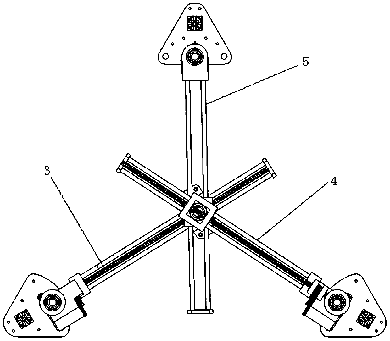
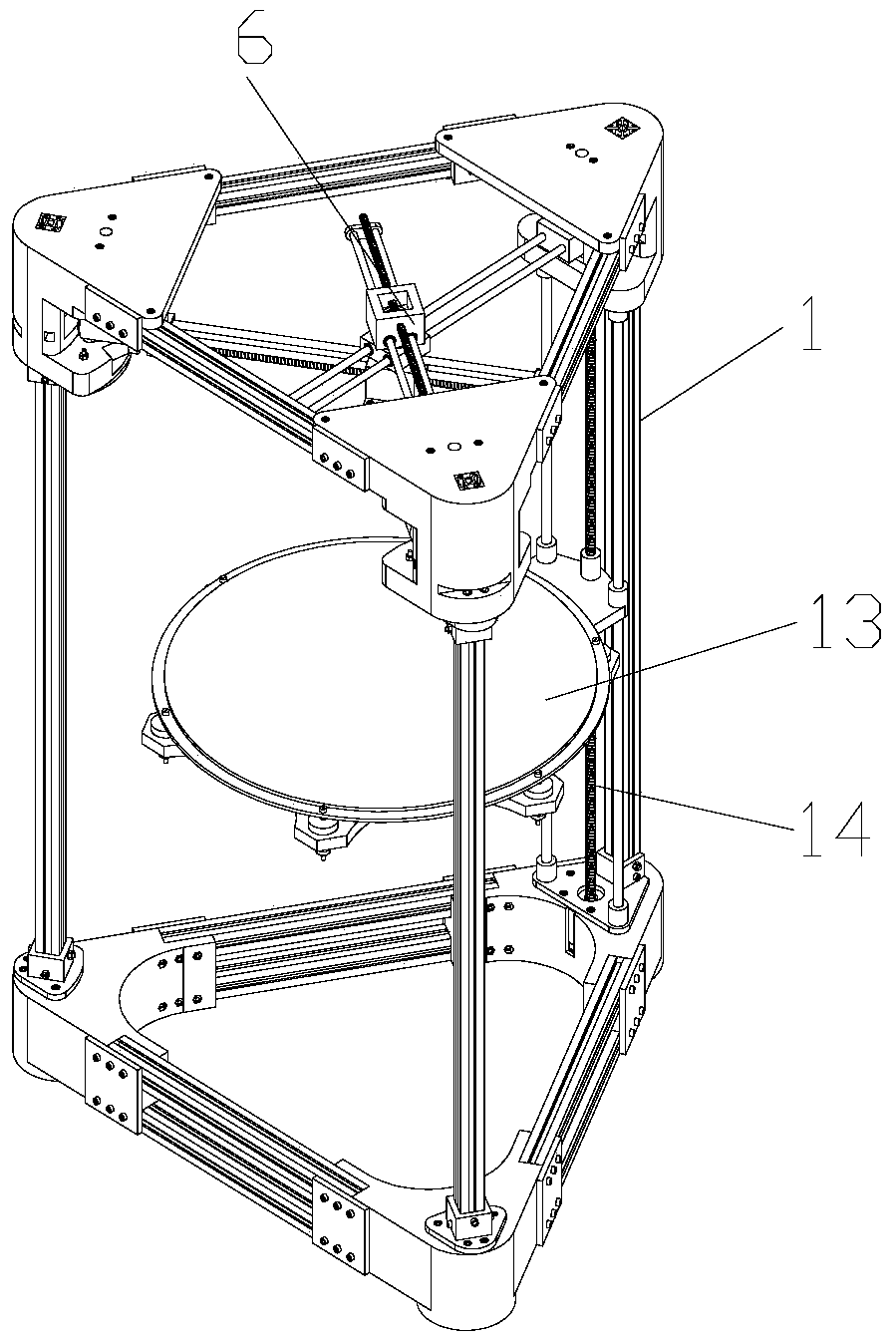
[0056] A 3D printer includes: a frame, a printing head, a plane driving mechanism, a printing platform, and an up and down driving mechanism.

[0057] The frame is a triangular column frame structure.

[0058] The planar drive mechanism includes: a first swing arm, a second swing arm, a third swing arm, a connecting body, a first position adjustment mechanism, and a second position adjustment mechanism. The first swing arm, the second swing arm, and the third swing arm all include a fixed end and a free end, and the three fixed ends distributed in a triangle are fixed on the frame through the rotating part, and the first, second, and third swing arms intersect The position of is the position where the connector is located. The connecting body includes the first sliding seat, the third sliding seat, and the second sliding seat arranged sequentially from top to bottom. On the connecting shaft, a locking screw is installed on the upper end of the connecting shaft, and a washer ...

Embodiment 2

[0066] In this embodiment, the first position adjustment mechanism and the second position adjustment mechanism have the same structure, both are swing drive mechanisms, including a motor, a transmission gear set, a herringbone gear and a spring or hairspring, the motor is fixed on the frame, and the herringbone The gear and the swing seat are fixed together; the motor drives the herringbone gear to rotate through the transmission gear set, the herringbone gear drives the swing seat to rotate, and the swing seat drives the first / second swing arm to rotate, so that the intersection of the first / second swing arm ( Connector) position is determined.

[0067] Figure 12 As shown, a backlash error elimination mechanism consisting of a spring and a herringbone gear is used. One end of the stretched spring is relatively fixed to the frame, and the other end is relatively fixed to the herringbone gear or the swing seat, so that the swing seat (together with the herringbone gear) ) al...


PUM


Abstract

The invention relates to a 3D printer, comprising a frame, a printing head and a planar driving mechanism that drives the printing head to move on a horizontal plane; the planar driving mechanism includes: a fixed end is connected to the frame through a rotating part, and a free end swings on a horizontal plane The first swing arm, the fixed end is connected with the frame through the rotating part, the second swing arm with the free end swinging on the horizontal plane, the connecting body of the print head is installed, and the first position adjustment mechanism for adjusting the swing position of the first swing arm is adjusted A second position adjustment mechanism for the swing position of the second swing arm; the connecting body includes a first sliding seat and a second sliding seat directly below the first sliding seat, and the first sliding seat and the second sliding seat rotate around the same vertical shaft; The first sliding seat slides along the first swing arm, and the second sliding seat slides along the second swing arm. The invention has the advantages of simple structure, improved printing accuracy and printing speed, and belongs to the technical field of 3D printers.

Description

technical field [0001] The invention relates to a 3D printer, in particular to a 3D printer with a movement mode different from that of a traditional printing head. Background technique [0002] The 3D printers currently on the market mainly have three mechanical structures, namely: Cartesian coordinate type, triangular claw (parallel arm) type, and steering gear rotation type (polar coordinate type). These are introduced below: [0003] (1) Cartesian coordinate type: [0004] The XYZ axes are at right angles to each other. The XY axes are usually positioned by a synchronous belt connected to a stepper motor, and the Z axis is controlled by a screw. The Cartesian coordinate type can be divided into two specific structures, namely the rectangular box structure and the rectangular rod (gantry) structure. [0005] 1. Rectangular box structure: [0006] The feature of this machine is that the hot bed moves along the Z-axis, and the object will not move in the XY-axis directi...

Claims


Application Information

Patent Timeline
Patent Type & Authority Patents(China)
IPC IPC(8): B29C64/236B29C64/205B29C64/245B29C64/241B33Y30/00
Inventor 徐开明吴桐李叶辉陈铭
Owner 徐开明
Learn More