
Wide-beam magnetic dipole antenna

A magnetic dipole antenna and magnetic dipole technology are applied in the direction of the connection of the antenna grounding switch structure and the structural form of the radiating element, which can solve the problems of narrow half-power beam, weak intensity, narrow beam, etc., and achieve wide application prospects, Simple structure, high gain effect

Active Publication Date: 2018-09-28
NANJING UNIV OF POSTS & TELECOMM
View PDF6 Cites 5 Cited by
  • Summary
  • Abstract
  • Description
  • Claims
  • Application Information

AI Technical Summary

Problems solved by technology

At present, the axial mode helical antenna is mostly used in satellite communication systems. This antenna has high gain and wide frequency bandwidth, but its beam is narrow, and the half-power beam width is only about 60°. When the satellite is not located in the beam of the ground receiving antenna When within the range, the signal will be transmitted to the antenna through multiple channels such as multipath fading. At this time, the strength becomes extremely weak and may even cause the ground system to stop receiving the signal
Therefore, in order to compensate for the low elevation gain of the ground receiving antenna, the antenna is usually designed as an active antenna, but the cost is increased
[0003] Microstrip patch antenna is the most widely used antenna in microwave systems, but the half-power beam of ordinary microstrip patch antenna is narrow (60° half-power beam is a typical value of microstrip patch antenna); The gain difference in the horizontal direction is more than 10dB, which cannot meet the wide beam requirements of satellite navigation antennas

Method used


Image

  • Wide-beam magnetic dipole antenna
  • Wide-beam magnetic dipole antenna
  • Wide-beam magnetic dipole antenna

Examples


Embodiment

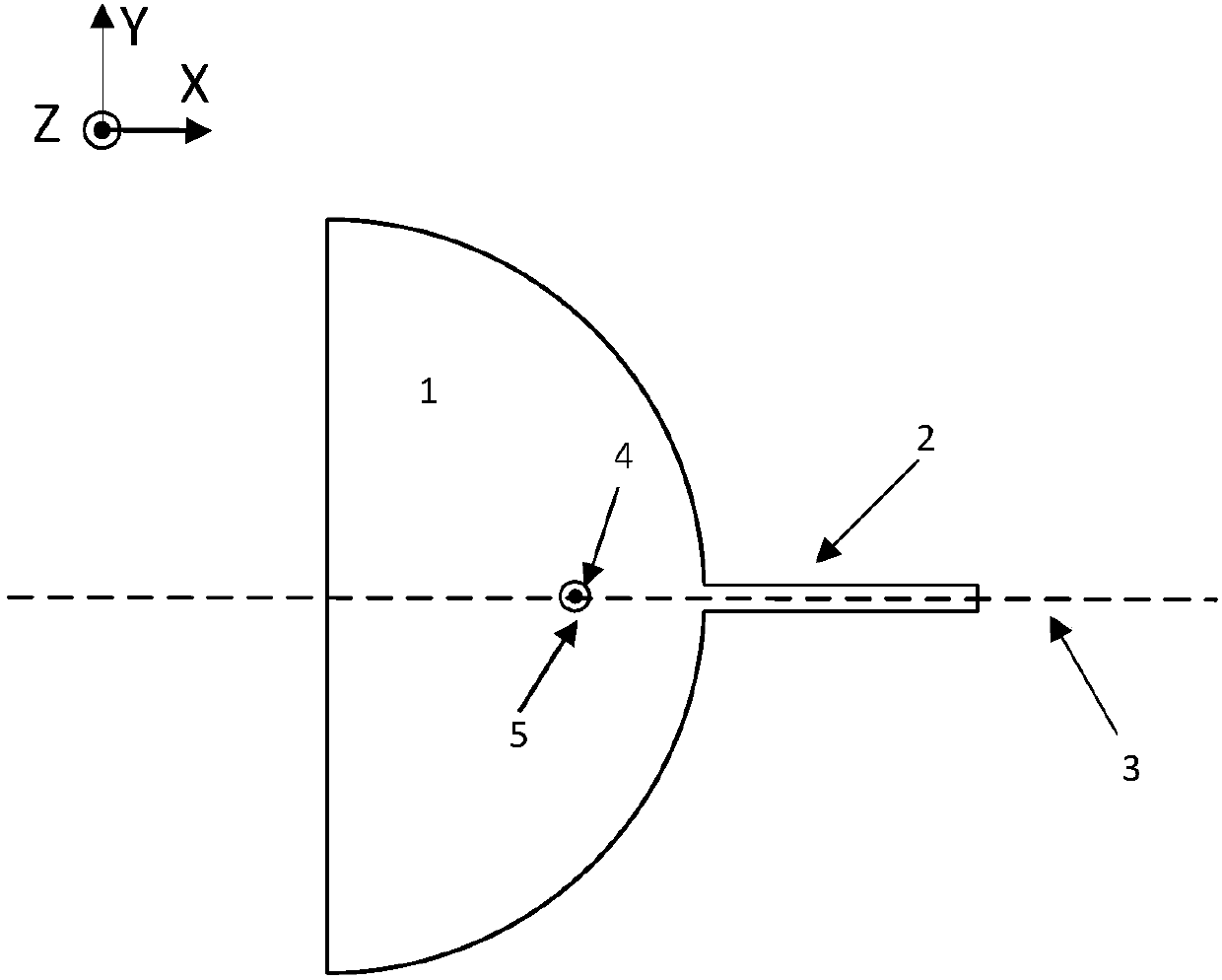
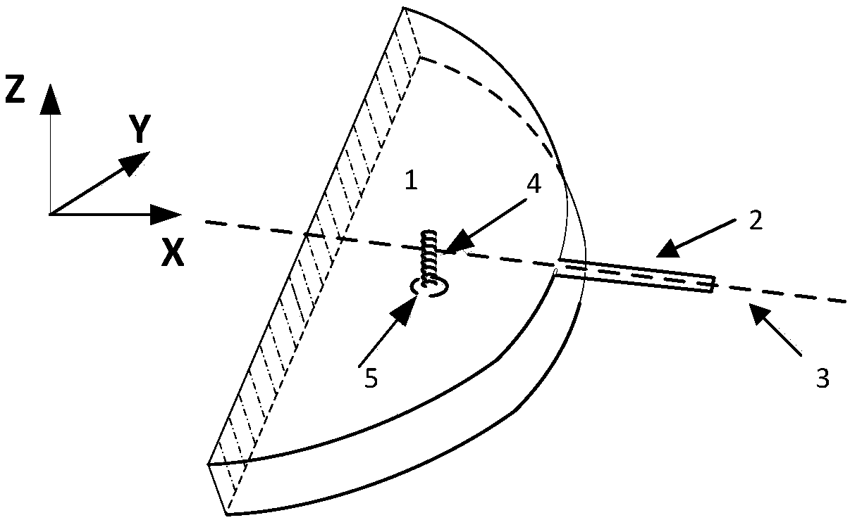
[0025] The overall radiation unit of the wide-beam magnetic dipole antenna in this embodiment is composed of a semicircular magnetic dipole structure 1 and a strip-shaped parasitic unit 2 . Semicircular magnetic dipole structure 1 is a non-closed structure consisting of two identical semicircular patches and a vertical short-circuit wall connecting the straight sides of the two semicircular patches. The semicircular magnetic dipole structure The upper surface of the unclosed end of 1 is connected with the elongated parasitic unit 2 .

[0026] In this embodiment, air medium is used, and the distance between the two semicircular patches on the upper and lower surfaces of the semicircular magnetic dipole structure 1 is 6 mm, and the radius of the semicircular magnetic dipole structure 1 is 36 mm, and the length The length and width of the strip-shaped parasitic unit 2 are 25mm and 2.4mm respectively, the angle between the strip-shaped parasitic unit 2 and the central axis 3 of th...


PUM


Abstract

The invention discloses a wide-beam magnetic dipole antenna, comprising a semicircular magnetic dipole structure and an elongated parasitic unit, wherein the semicircular magnetic dipole structure comprises two semicircular patches of the same radius and a vertical short circuit wall, the two semicircular patches are symmetrically placed in parallel up and down, and the vertical short circuit wallis connected to the two semicircular patches along the diameter direction of the semicircular patches; the elongated parasitic unit is placed along the central axis of the semicircular magnetic dipole structure, and is connected to the upper surface of the semicircular magnetic dipole structure; and the semicircular magnetic dipole structure is in a non-fully enclosed structure. The invention hasthe characteristics of small volume, high gain, low profile and simple structure, and has wide application prospects in various wireless sensing and radio frequency identification systems of the Internet of Things.

Description

technical field [0001] The invention belongs to the Internet of Things and microwave technology, in particular to a wide-beam magnetic dipole antenna. Background technique [0002] In satellite communication, in order to meet the needs of communication, the ground mobile communication terminal antenna is generally required to have the performance characteristics of wide beam. At present, the axial mode helical antenna is mostly used in satellite communication systems. This antenna has high gain and wide frequency bandwidth, but its beam is narrow, and the half-power beam width is only about 60°. When the satellite is not located in the beam of the ground receiving antenna When within the range, the signal will be transmitted to the antenna through multiple channels such as multipath fading. At this time, the strength becomes extremely weak and may even cause the ground system to stop receiving the signal. Therefore, in order to compensate for the low elevation gain of the g...

Claims


Application Information

Patent Timeline
Patent Type & Authority Applications(China)
IPC IPC(8): H01Q1/36H01Q1/50
CPCH01Q1/36H01Q1/50
Inventor 吕文俊李壮李笑乾张伟丽顾珊珊邵芸朱洪波
Owner NANJING UNIV OF POSTS & TELECOMM
Learn More