Eureka AIR delivers breakthrough ideas for toughest innovation challenges, trusted by R&D personnel around the world.

A New Transformer Protective Shell with Monitoring Function

A new technology for transformer protection, applied in transformer/inductor housing, transformer/inductor cooling, transformer/inductor components, etc., can solve the problem that the transformer cannot be monitored in the background, the heat dissipation area of Self-protection devices and other issues to achieve the effect of expanding the heat dissipation area

Active Publication Date: 2020-06-12
江苏多维智能科技有限公司
View PDF4 Cites 0 Cited by
  • Summary
  • Abstract
  • Description
  • Claims
  • Application Information

AI Technical Summary

Problems solved by technology

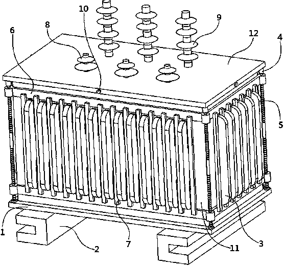
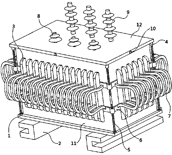
[0004] Aiming at the deficiencies of the prior art, the present invention provides a new type of transformer protection shell with monitoring function, which realizes the deformation of the buffer zone through the proximity of two protection frames, and solves the problem that the transformer shell does not have an independent protection device; the heat dissipation block passes through The deformation of the buffer zone realizes the displacement, which solves the problem that the heat dissipation area of ​​the transformer shell cannot be expanded; through the communication module in the controller, the problem that the transformer cannot be monitored in the background is solved

Method used


Image

  • A New Transformer Protective Shell with Monitoring Function
  • A New Transformer Protective Shell with Monitoring Function
  • A New Transformer Protective Shell with Monitoring Function

Examples


Embodiment Construction

[0028] The technical solutions in the embodiments of the present invention will be clearly and completely described below with reference to the accompanying drawings in the embodiments of the present invention. Obviously, the described embodiments are only a part of the embodiments of the present invention, but not all of the embodiments. Based on the embodiments of the present invention, all other embodiments obtained by those of ordinary skill in the art without creative efforts shall fall within the protection scope of the present invention.

[0029] In the description of the present invention, it is to be understood that the terms "opening", "upper", "lower", "thickness", "top", "middle", "length", "inside", "around", etc. Indicates the orientation or positional relationship, only for the convenience of describing the present invention and simplifying the description, rather than indicating or implying that the components or elements referred to must have a specific orienta...


PUM

PropertyMeasurementUnit
widthaaaaaaaaaa
depthaaaaaaaaaa
lengthaaaaaaaaaa

Abstract

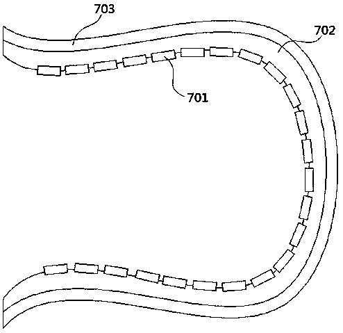
The invention discloses a novel transformer protection casing with a monitoring function, and relates to the technical field of substation equipment. The novel transformer protection casing with the monitoring function comprises a base; one surface of the base is fixed with a quantity of padding iron, and one surface of the base is fixed with a middle frame; a plurality of cooling fins are fixed on the peripheral surface of the middle frame, and one surface of the middle frame is fixed with an upper cover; one surface of the upper cover is fixedly connected with a plurality of driving devices;one end of the output shaft of the driving device is fixedly connected with a screw; one end of the screw is rotatably connected with one surface of the base; the peripheral surface of the screw is in threaded connection with a plurality of protective frames; buffer belts are fixedly connected between the opposite surfaces of the multiple protective frames; a plurality of low-voltage bushings arefixedly connected with one surface of the upper cover; and one surface of the upper cover is fixedly connected with a plurality of high-voltage bushings. The novel transformer protection casing withthe monitoring function in the invention realizes the deformation of the buffer belt through the proximity of a plurality of protective frames; the protective frame enables the novel transformer casing having autonomous protection kinetic energy; and the buffer belt has the advantage of expanding the heat dissipation area of the transformer casing.

Description

technical field [0001] The invention relates to the technical field of substation equipment, in particular to a novel transformer protective casing with monitoring function. Background technique [0002] The transformer is a device that uses the principle of electromagnetic induction to change the AC voltage. The main components are the primary coil, the secondary coil and the iron core. The main functions are: voltage transformation, current transformation, impedance transformation, isolation, voltage regulation, etc. According to the purpose, it can be divided into electric furnace transformer, rectifier transformer, power frequency test transformer, voltage regulator, mining transformer, audio transformer, intermediate frequency transformer, high frequency transformer, impulse transformer, instrument transformer, electronic transformer, reactor, transformer, etc. , Transformers can be divided into dry-type transformers and oil-immersed transformers according to the heat d...

Claims


Application Information

Patent Timeline
Patent Type & Authority Patents(China)
IPC IPC(8): H01F27/02H01F27/06H01F27/22H01F27/40
CPCH01F27/025H01F27/06H01F27/22H01F27/40H01F27/402H01F2027/406
Inventor 辛成辉
Owner 江苏多维智能科技有限公司
Why Eureka
Eureka Blog
Learn More