
Method for expanding holographic retinal imaging of angle of view

A retina and field of view technology, applied in the field of holographic imaging, can solve problems such as small field of view, reconstructed image speckles, and difficult liquid crystal crosstalk, and achieve the effect of improving brightness and expanding field of view

Inactive Publication Date: 2018-09-28
SOUTHEAST UNIV
View PDF6 Cites 5 Cited by
  • Summary
  • Abstract
  • Description
  • Claims
  • Application Information

AI Technical Summary

Problems solved by technology

However, the traditional holographic display technology is limited by the spatial light modulator pixel pitch and device size, resulting in a small field of view
When the human eye moves slightly, it will deviate from the imaging position, blocked by the diaphragm or interfered by other high-diffraction orders, and cannot see a clear reconstruction scene, which greatly hinders the application scenarios of holographic retinal imaging technology
In order to solve this problem, the existing research starts from the device technology to produce a spatial light modulator with a smaller pixel pitch, which can increase the viewing angle, but in this way, for the commonly used liquid crystal spatial light modulator , the crosstalk between liquid crystals will bring new problems
On the other hand, the existing holographic display technology mostly uses laser as the illumination source, but the laser wavelength range is extremely small, that is, the coherence is very high, which will cause serious speckle in the reconstructed image and affect the imaging quality. Therefore, urgent A new solution is needed to solve this technical problem

Method used


Image

  • Method for expanding holographic retinal imaging of angle of view
  • Method for expanding holographic retinal imaging of angle of view
  • Method for expanding holographic retinal imaging of angle of view

Examples


Embodiment 1

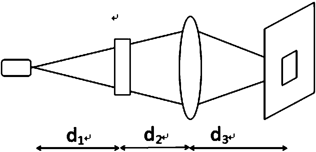
[0053] Embodiment 1: as figure 1 , figure 2 , image 3 As shown, a holographic retinal imaging method for expanding the field of view, comprising the following steps:

[0054] Step 1) Calculate the phase-only hologram of the object, and its specific calculation process is as follows:

[0055] According to formula (1), any two-dimensional complex amplitude light field is expressed by the following formula:

[0056]

[0057] Among them, A represents the amplitude distribution of the object (here it is assumed that the input is a two-dimensional image), and z represents the curvature radius of each spherical wave, that is, the distance from the reconstructed object to the holographic surface. U represents the complex amplitude distribution of spherical waves with unit amplitude, which is given by equation (2):

[0058]

[0059] where λ represents the wavelength.

[0060] The sampling condition of the spherical wave light field is given by formula (3):

[0061]

[00...


PUM


Abstract

The invention discloses a method for expanding holographic retinal imaging of an angle of view, comprising the steps of: 1) calculating a hologram of an object; 2) determining parameters in the optical system, such as a spacing between several point sources, sampling pitch and resolution of a spatial light modulator, focal length of a lens, and position of a filter; 3) laying out a projection device: sequentially arranging a light source group composed of several point light sources, the spatial light modulator, the lens and the filter, wherein the spatial light modulator is connected with a computer; and 4) transmitting the phase hologram to the spatial light modulator through the computer, and then using the spatial light modulator to project the phase hologram into the observer's eyes at a specified position. The holographic retinal imaging method is capable of effectively expanding the field of view of the reconstructed image on the basis of ensuring the quality of the reconstructed image.

Description

technical field [0001] The invention relates to a holographic retinal imaging method for enlarging the viewing angle, and belongs to the technical field of holographic imaging. Background technique [0002] Compared with traditional 3D display technology, holographic display technology is a technology capable of reconstructing the complex amplitude light field of an object, and is therefore considered to be the most ideal next-generation 3D display technology. However, the traditional holographic display technology is limited by the spatial light modulator pixel pitch and device size, resulting in a small field of view. When the human eye moves slightly, it will deviate from the imaging position, be blocked by the diaphragm or interfered by other high diffraction orders, and cannot see a clear reconstruction scene, which greatly hinders the application scenarios of holographic retinal imaging technology. In order to solve this problem, the existing research starts from the ...

Claims


Application Information

Patent Timeline
IPC IPC(8): G03H1/22G03H1/32
CPCG03H1/22G03H1/32
Inventor 庞宇燕夏军
Owner SOUTHEAST UNIV
Learn More