
Drying device for chemical fiber cloth

A drying device and cloth technology, applied in the directions of drying, drying machine, drying gas arrangement, etc., can solve the problems of slow drying rate, etc., and achieve the effects of improving production efficiency, ensuring heat dissipation performance, and improving drying rate

Inactive Publication Date: 2018-09-28
侯如升
View PDF0 Cites 4 Cited by
  • Summary
  • Abstract
  • Description
  • Claims
  • Application Information

AI Technical Summary

Problems solved by technology

[0002] Chemical fiber is made of natural polymer compound or artificially synthesized polymer compound as raw material, through the preparation of spinning dope, spinning and post-processing and other processes to produce fibers with textile properties. Chemical fibers should have light resistance, wear resistance, and easy washing The characteristics of easy drying, its chemical fiber fabrics are also widely used in the manufacturing industry of clothing fabrics; in the process of making chemical fiber fabrics, rinsing and drying are generally carried out, but when the traditional chemical fiber fabrics are dried, they are all After rinsing, the chemical fiber fabrics are directly put into the drying box for drying, resulting in a slow drying rate, so this needs to be improved

Method used


Image

  • Drying device for chemical fiber cloth
  • Drying device for chemical fiber cloth

Examples


Embodiment Construction

[0019] The following will clearly and completely describe the technical solutions in the embodiments of the present invention with reference to the accompanying drawings in the embodiments of the present invention. Obviously, the described embodiments are only some, not all, embodiments of the present invention. Based on the embodiments of the present invention, all other embodiments obtained by persons of ordinary skill in the art without making creative efforts belong to the protection scope of the present invention.

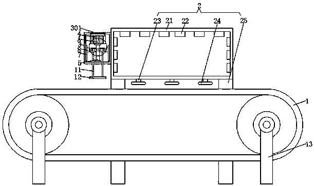
[0020] Such as Figure 1-2 As shown, the embodiment of the present invention provides a drying device for chemical fiber cloth, including a conveyor belt 1, a drying mechanism 2 is arranged on one side of the conveyor belt 1, and an exhaust fan is arranged inside the drying mechanism 2. Since the exhaust fan is The existing device is relatively simple, so it is not shown in the figure. The drying mechanism 2 includes a casing 21. On the inner wall of the casin...


PUM


Abstract

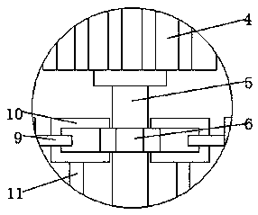
The invention provides a drying device for chemical fiber cloth. The drying device comprises a conveying belt, a drying mechanism is arranged on one side of the conveying belt, a shell is welded to one side of the drying mechanism, a motor is fixedly installed at the top of the inner cavity of the shell, one end of a rotating shaft of the motor is in transmission connection with a threaded rod through a coupling, the outer surface of the threaded rod is in threaded connection with a threaded sleeve pipe, the two sides of the inner wall of the shell are connected with sliding blocks through sliding rails in a sliding mode, first connecting rods are welded to one sides of the sliding blocks, second connecting rods are welded to the two sides of each first connecting rod, furthermore, supporting rods are welded at the bottoms of the second connecting rods located on the lower sides, and a pressing plate is fixedly connected between the two supporting rods. According to the drying device for the chemical fiber cloth, the motor, the threaded rod and the threaded sleeve are arranged and cooperate with the sliding rails and the sliding blocks as well as the first connecting rods and the second connecting rods, and therefore, the pressing plate can be used for squeezing water thoroughly on the rinsed chemical fiber cloth, then drying is carried out on the chemical fiber cloth, and thedrying rate of the chemical fiber cloth is improved.

Description

technical field [0001] The invention relates to the technical field of chemical fiber, in particular to a drying device for chemical fiber cloth. Background technique [0002] Chemical fiber is made of natural polymer compound or artificially synthesized polymer compound as raw material, through the preparation of spinning dope, spinning and post-treatment, and other processes to produce fibers with textile properties. Chemical fibers should be light-resistant, wear-resistant, and easy to wash The characteristics of easy drying, its chemical fiber fabrics are also widely used in the manufacturing industry of clothing fabrics; in the process of making chemical fiber fabrics, it is generally rinsed and dried, but when the traditional chemical fiber fabrics are dried, they are all The rinsed chemical fiber fabrics are directly put into the drying box for drying, resulting in a slow drying rate, so it needs to be improved. Contents of the invention [0003] (1) Solved technic...

Claims


Application Information

Patent Timeline
IPC IPC(8): F26B13/02F26B13/28F26B21/00F26B25/00
CPCF26B13/00F26B13/28F26B21/001F26B21/004F26B25/00
Inventor 侯如升
Owner 侯如升
Learn More