
Tunneling machine and water jet nozzle thereof

A technology of water jets and nozzles, applied in mining equipment, earthwork drilling, tunnels, etc., can solve the problems of limiting the working pressure and flow rate of high-pressure nozzles, poor applicability, small cutting surface, etc., to reduce the frequency of replacing water jet nozzles, Improve tunneling efficiency and increase the effect of application occasions

Pending Publication Date: 2018-09-28
CHINA RAILWAY CONSTR HEAVY IND
View PDF0 Cites 5 Cited by
  • Summary
  • Abstract
  • Description
  • Claims
  • Application Information

AI Technical Summary

Problems solved by technology

For example, some high-pressure nozzles cannot rotate and can only be used for directional cutting, especially for hand-held water jet cutting nozzles, the cutting surface is small, and such nozzles seriously affect cutting efficiency
For another example, although some high-pressure nozzles can be rotated, it is usually necessary to add a rotary sealing component at the rotation junction. Correspondingly, the quality of the rotary sealing component seriously limits the working pressure and flow rate of the high-pressure nozzle, thus affecting the cutting efficiency.
In addition, the structural design of some high-pressure nozzles is unreasonable. For example, the effective cutting area of ​​the high-pressure nozzle is smaller than the cross-sectional area of ​​the high-pressure nozzle body, resulting in a limited cutting depth, which makes it impossible to use this type of high-pressure nozzle for cutting with a large thickness.
Therefore, the applicability of the existing high-pressure nozzles is relatively poor

Method used


Image

  • Tunneling machine and water jet nozzle thereof
  • Tunneling machine and water jet nozzle thereof
  • Tunneling machine and water jet nozzle thereof

Examples


Embodiment Construction

[0045] The following will clearly and completely describe the technical solutions in the embodiments of the present invention with reference to the accompanying drawings in the embodiments of the present invention. Obviously, the described embodiments are only some, not all, embodiments of the present invention. Based on the embodiments of the present invention, all other embodiments obtained by persons of ordinary skill in the art without making creative efforts belong to the protection scope of the present invention.

[0046] In order to enable those skilled in the art to better understand the solution of the present invention, the present invention will be further described in detail below in conjunction with the accompanying drawings and specific embodiments.

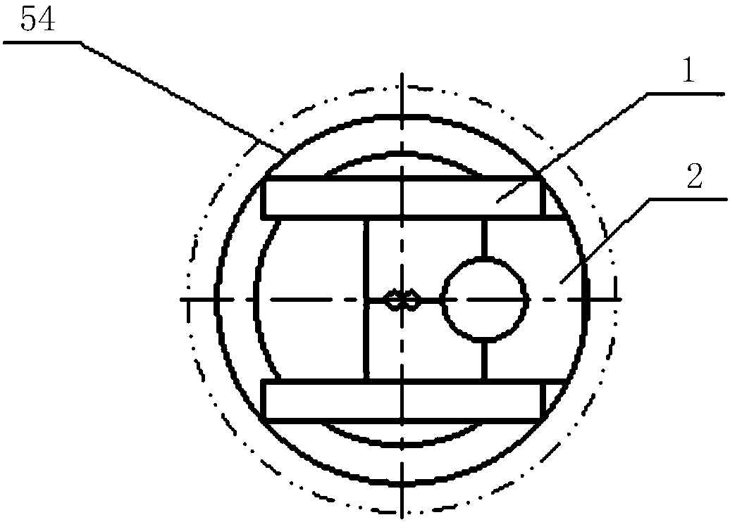
[0047] Please refer to Figure 1 to Figure 3 , figure 1 A sectional front view of a water jet nozzle provided by a specific embodiment of the present invention; figure 2 A cross-sectional front view of a water je...


PUM


Abstract

The invention discloses a water jet nozzle. The water jet nozzle comprises a connecting frame, and further comprises a support frame, a rotating driving portion and a high-pressure water pipeline. Thesupport frame is fixed to the lower side of the connecting frame, the rotating driving portion is mounted on the support frame, one end of the high-pressure water pipeline is fixed to the support frame through a pipe clamp, and the other end of the high-pressure water pipeline penetrates from the interior of the rotating driving portion and can swing relative to the support frame. By using the water jet nozzle, rotary cutting of high-pressure water inside the high-pressure water pipeline is realized under the action of the pipe clamp and the rotating driving portion, the cutting area is increased, the cutting efficiency is improved, and the cutting requirement of higher efficiency is met; and at the same time, the high-pressure water flows out directly through the high-pressure water pipeline, setting of rotary sealing is not required, the limitation of a rotary sealing structure and the strength on the pressure and flow of the high-pressure water is eliminated, and the cutting requirement of greater pressure is met. Therefore, the water jet nozzle has better adaptability. The invention further discloses a tunneling machine including the water jet nozzle, and the tunneling efficiency is improved.

Description

technical field [0001] The invention relates to the technical field of water jet cutting, in particular to a water jet nozzle. The invention also relates to a boring machine. Background technique [0002] As an environmentally friendly and efficient cold processing technology, water jet cutting technology usually uses the impact of high-pressure and high-speed water flow on the product to remove materials. Compared with traditional cutting methods, it has the advantages of small thermal deformation of materials, high cutting precision and fast cutting speed. , Widely used in engineering, automobile, aviation, food and other fields. [0003] Water jet cutting machines usually include components such as booster components, feed pipes, control components, and high-pressure nozzles. The high-pressure water flowing out of the booster components is directly sprayed from the high-pressure nozzle, or the high-pressure water and abrasives are mixed in the high-pressure nozzle to for...

Claims


Application Information

Patent Timeline
IPC IPC(8): E21D9/10
CPCE21D9/1066
Inventor 刘飞香程永亮祝爽陈望唐崇茂蒋海华廖金军易达云王堃徐震刘志友
Owner CHINA RAILWAY CONSTR HEAVY IND
Learn More