Seat headrest with loudspeaker

A loudspeaker and headrest technology, which is applied to vehicle seats, sensors, special positions of the vehicle, etc., can solve the problems of impacting the head of passengers or drivers, large volume of loudspeakers or horns, and increased distortion of loudspeakers, etc., to achieve enhanced Loudness of sound, small size of speaker, good sound quality

Pending Publication Date: 2018-09-28
黄清山
View PDF25 Cites 0 Cited by
  • Summary
  • Abstract
  • Description
  • Claims
  • Application Information

AI Technical Summary

Problems solved by technology

[0003] Taking a car as an example, when the car is driving on the highway, for some vehicles with poor sound insulation effect, the noise inside the car will be very loud, and the sound effect produced by the ordinary central control horn of the car cannot cover the outside of the car. In this way, the sound effect in the car is useless. In addition, when there are multiple passengers in the car, different passengers have different preferences for music or different needs for speakers, and often cannot meet the needs of each passenger at the same time. , the sounding headrest with a horn device installed in the seat headrest can meet the needs of passengers
[0004] my country has strict regulations on the seat headrests of vehicles, but the existing headrests with loudspeakers have a very complicated structure, and the volume of the speakers or horns is too large. When an accident occurs in the vehicle, the seat The loudspeaker in the headrest is too large, it is easy to throw out and hit the head of the passenger or driver, which may cause fatal injury. Therefore, the volume of the loudspeaker can only be reduced in the same proportion, but the power is reduced when the volume is reduced, resulting in insufficient sound loudness , can not meet the requirements, and at the same time, it also increases the distortion rate of the speaker and greatly reduces the quality of the sound. Therefore, there is no safe and sound-effective seat headrest on the market.

Method used


Image

  • Seat headrest with loudspeaker
  • Seat headrest with loudspeaker
  • Seat headrest with loudspeaker

Examples


Embodiment Construction

[0026] The present invention is further described in conjunction with the following examples.

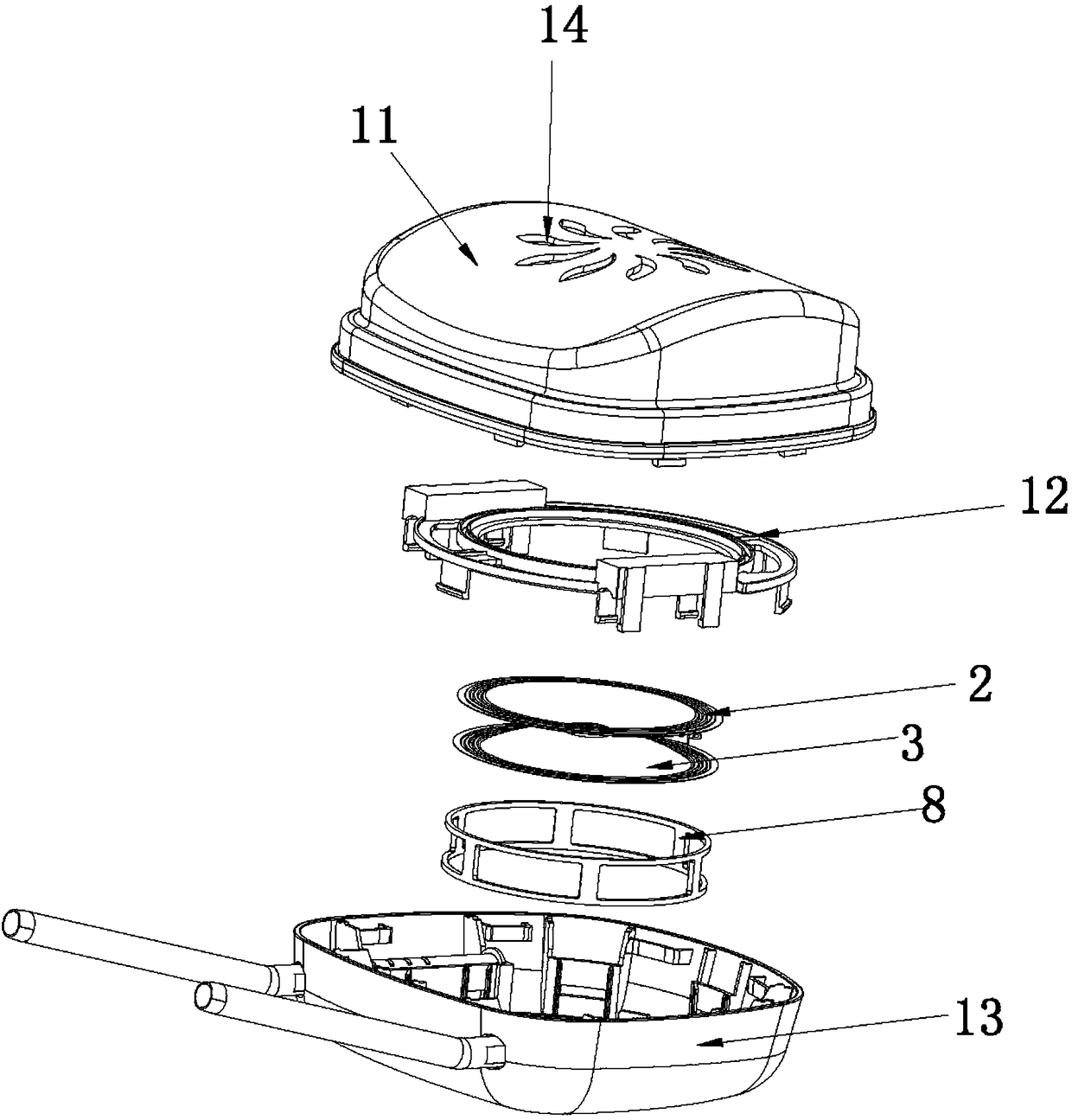
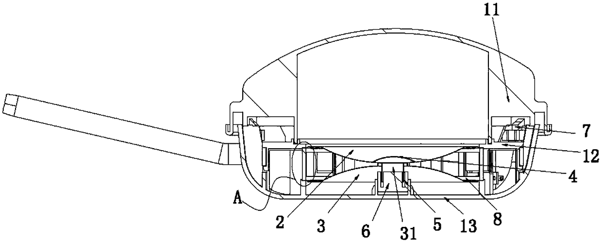
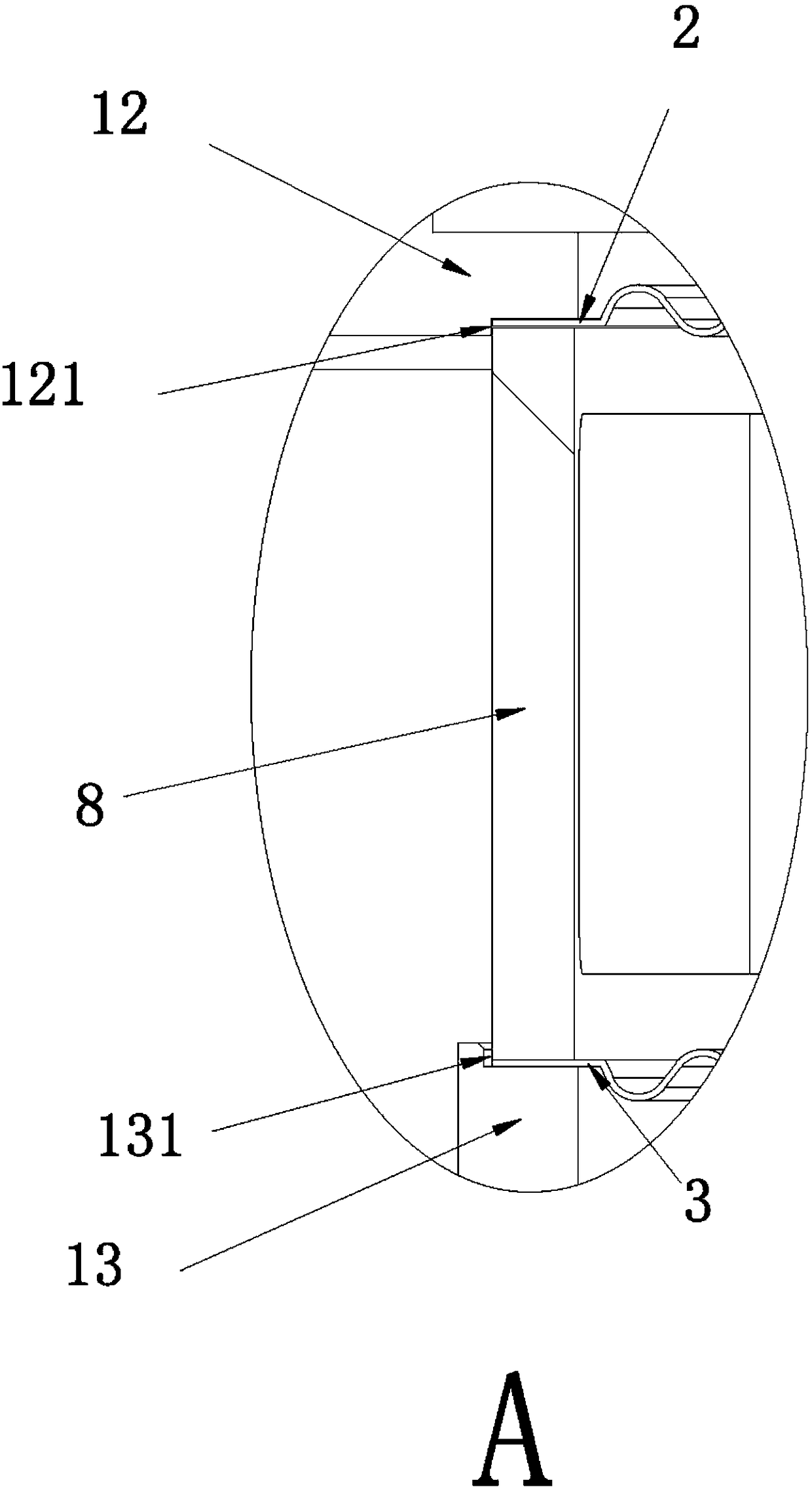
[0027] The specific embodiment of the loudspeaker of the present invention, as Figure 1 to Figure 7 As shown, the horn includes a drum paper assembly, a headrest housing, a voice coil 5, a ring magnet 6, an audio device 7 and a dust cover 4, specifically, the headrest housing includes an upper cover 11, a fixing bracket 12 and a lower cover 13 , in this embodiment, in order to facilitate the production and the maintenance and detection of the speaker, the detachable connection between the upper cover 11 and the lower cover 13 is in the form of clamping, of course, it can also be realized by threaded connection with screws The detachable connection, specifically, can be selected according to actual needs. In addition, the fixed bracket 12 is fixedly installed inside the headrest shell, and the fixed bracket 12 is clamped and connected with the lower cover 13 to form a container for ...


PUM


Abstract

The invention relates to the technical field of seat headrests, in particular to a seat headrest with a loudspeaker. The seat headrest comprises a drum paper component, a headrest shell, a voice coil,an annular magnet, an audio frequency device and a dustproof cover. The drum paper component comprises an annular support, upper drum paper and lower drum paper, the upper drum paper and the lower drum paper are each arranged in a horn shape and are centrally symmetrically arranged, wave crests of the upper drum paper and the lower drum paper are opposite and are bonded to form the drum paper component, and the annular support is arranged between the upper drum paper and the lower drum paper and abuts against the edges of the upper drum paper and the lower drum paper. Compared with the priorart, double drum paper formed through the upper drum paper and the lower drum paper which are centrally symmetrically arranged substitutes single-layer drum paper adopted in the prior art, the size ofthe loudspeaker is effectively reduced, meanwhile, the loudness of sound is increased as well, the distortion rate of the loudspeaker is reduced as well, and the quality of sound is greatly improved.

Description

technical field [0001] The invention relates to the technical field of seat headrests, in particular to a seat headrest with a loudspeaker. Background technique [0002] Loudspeakers, also known as horns, are widely used in various audio equipment as electro-acoustic conversion devices. With the development of science and technology and the needs of customers, under the trend of miniaturization of electronic products, consumers also turn their attention to vehicles, high-speed rails, airplanes and other means of transportation. [0003] Taking a car as an example, when the car is driving on the highway, for some vehicles with poor sound insulation effect, the noise inside the car will be very loud, and the sound effect produced by the ordinary central control horn of the car cannot cover the outside of the car. In this way, the sound effect in the car is useless. In addition, when there are multiple passengers in the car, different passengers have different preferences for ...

Claims


Application Information

Patent Timeline
Patent Type & Authority Applications(China)
IPC IPC(8): B60N2/879H04R9/06
CPCH04R9/06B60N2/879
Inventor 黄清山
Owner 黄清山
Why Eureka
Try Eureka