
Annular heat radiator assembly fixture

A technology for annular radiators and assembly fixtures, which is applied in the direction of manufacturing tools, workpiece clamping devices, and drilling molds for workpieces, etc., can solve problems such as difficulty in ensuring accuracy, time-consuming, and affecting product assembly accuracy and efficiency. Achieve the effect of meeting installation requirements, improving assembly accuracy and assembly efficiency

Active Publication Date: 2018-09-28
GUIZHOU YONGHONG AVIATION MACHINERY
View PDF5 Cites 7 Cited by
  • Summary
  • Abstract
  • Description
  • Claims
  • Application Information

AI Technical Summary

Problems solved by technology

[0003] In the existing technology, there is no mature technology available that can ensure the radial step difference between the inner profile of the annular radiator and the inner profile of the engine interface during the product assembly process. Generally, the coaxiality is tested multiple times during the processing process. During the detection process, it is continuously adjusted until the coaxiality requirement is met. This method is difficult to guarantee the accuracy and requires extremely high proficiency of the processing personnel.
Therefore, it is difficult to ensure the coaxiality between the installation connection hole of the annular radiator and the centerline of the inner cylinder surface, which often consumes a lot of time and labor, and seriously affects the assembly accuracy and efficiency of the product.

Method used


Image

  • Annular heat radiator assembly fixture
  • Annular heat radiator assembly fixture
  • Annular heat radiator assembly fixture

Examples


Embodiment Construction

[0032] The technical solution of the present invention is further described below in conjunction with the accompanying drawings, but the scope of protection is not limited to the description.

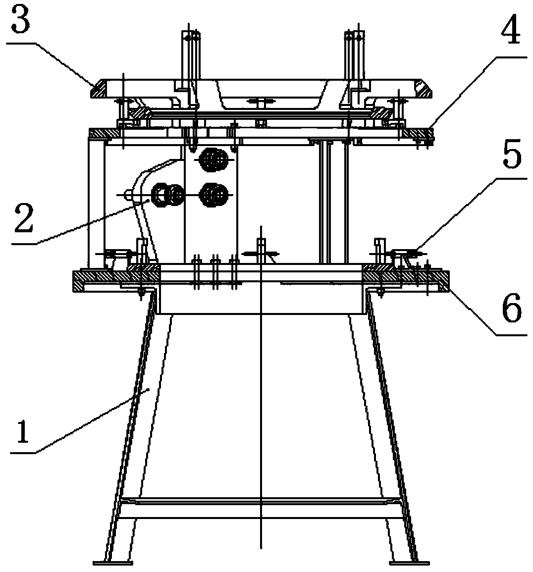
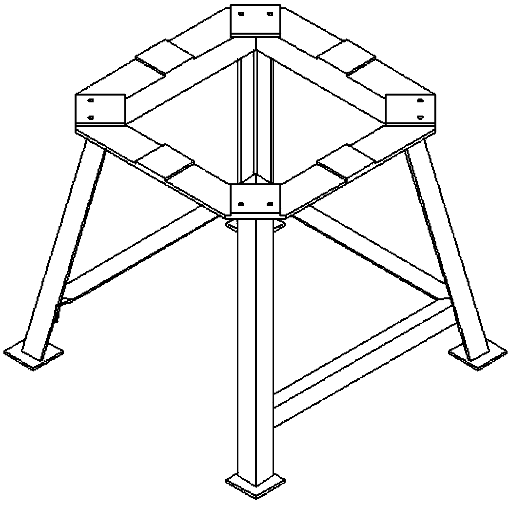
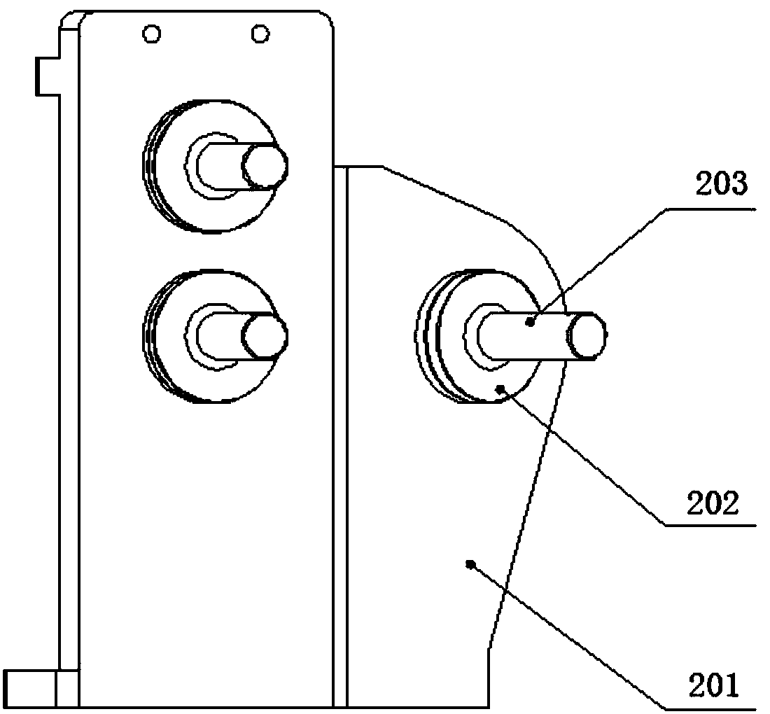
[0033] Such as Figure 1-13 As shown, a ring-shaped radiator assembly fixture according to the present invention includes a bracket assembly 1, a hot and cold nozzle positioning assembly 2, a transfer positioning plate assembly 3, an upper positioning ring assembly 4 and a lower positioning ring assembly 6. The lower positioning ring assembly 6 is installed on the upper end of the bracket assembly 1, the upper positioning ring assembly 4 is fixed on the lower positioning ring assembly 6, and the hot and cold nozzle positioning assembly 2 is installed between the lower positioning ring assembly 6 and the upper positioning ring assembly 4 The upper ends of the lower positioning ring assembly 6 and the upper positioning ring assembly 4 are respectively provided with a plurality of compacto...


PUM


Abstract

The invention discloses an annular heat radiator assembly fixture, which belongs to the technical field of aviation heat radiation. The annular heat radiator assembly fixture comprises a support assembly, a hot and cold pipe nozzle positioning assembly, an adapter positioning plate assembly, an upper positioning ring assembly and a lower positioning ring assembly. The lower positioning ring assembly is arranged at the upper end of the support assembly; the upper positioning ring assembly is fixed onto the lower positioning ring assembly; the hot and cold pipe nozzle positioning assembly is arranged between the lower positioning ring assembly and the upper positioning ring assembly; a plurality of presser assemblies are arranged at the upper ends of the lower positioning ring assembly and the upper positioning ring assembly; and the adapter positioning plate assembly is arranged at the upper end of the upper positioning ring assembly. According to the technical scheme, an annular heat radiator front ring assembly is positioned through the lower positioning ring assembly, a product inner cylinder molded surface and a valve ring assembly are positioned through the adapter positioningplate assembly, and various parts are preliminarily clamped and fixed through the presser assemblies, so that locking is realized after the accuracy requirement is met through adjustment, and guiding,drilling, detecting, assembling and riveting are accurately and high-efficiently accomplished.

Description

technical field [0001] The invention belongs to the technical field of aviation heat dissipation, and relates to an installation technology of an aviation radiator, in particular to an assembly fixture of an annular radiator. Background technique [0002] The annular radiator is used to cool the high-temperature air from the primary radiator, and is one of the main cooling components of the aircraft environmental control system. The annular radiator is installed in the aircraft accessory casing compartment, the front end is connected with the air intake, and the rear end is connected with the engine. When assembling, there are two important indicators to be guaranteed between the end face of the annular radiator and the end face of the engine: one is the end face clearance requirement, because the end face of the product has a margin, it can be repaired on site according to the requirements, so the quality is easy to guarantee; the second is the internal shape of the annular...

Claims


Application Information

Patent Timeline
Patent Type & Authority Applications(China)
IPC IPC(8): B25B11/00B25B11/02B23B47/28
CPCB23B47/28B25B11/00B25B11/02
Inventor 孙德明邓茂贵廖前进
Owner GUIZHOU YONGHONG AVIATION MACHINERY
Learn More