Method and device for removing plasma cloud

A technology of plasma cloud and equipment, applied in the field of ion cloud, can solve the problem of inability to quickly remove the plasma cloud, and achieve the effects of reducing internal stress, reducing cooling speed, and eliminating shrinkage cavities

Inactive Publication Date: 2018-09-28
GUANGDONG ZHENGYE TECH
View PDF10 Cites 2 Cited by
  • Summary
  • Abstract
  • Description
  • Claims
  • Application Information

AI Technical Summary

Problems solved by technology

[0004] In view of the above-mentioned deficiencies in the prior art, the object of the present invention is to provide a method and equipment for removing plasma cloud, aiming at solving the problem that the existing laser processing technology cannot quickly remove the plasma cloud inside the molten pool

Method used


Image

  • Method and device for removing plasma cloud
  • Method and device for removing plasma cloud
  • Method and device for removing plasma cloud

Examples


Embodiment Construction

[0024] The present invention provides a method and equipment for removing plasma clouds. In order to make the purpose, technical solution and effect of the present invention clearer and clearer, the present invention will be further described in detail below. It should be understood that the specific embodiments described here are only used to explain the present invention, not to limit the present invention.

[0025] A preferred embodiment of a device for removing plasma clouds of the present invention includes a control host 1 and an induction coil 2 positioned above the plasma clouds, such as image 3 As shown, the control host is electrically connected to the induction coil, and the control host controls the induction coil to generate an alternating magnetic field for removing the plasma cloud.

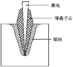
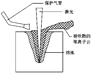
[0026] In a plasma cloud, the direction of ion motion is random, so there is a half-possibility of moving outward. After increasing the magnetic field, the magnetic field distrib...


PUM


Abstract

The invention discloses a method and device for removing a plasma cloud. The device comprises a control host and an induction coil which is electrically connected with the control host; the inductioncoil is located over the plasma cloud; and the control host controls the induction coil to generate an alternating magnetic field used for removing the plasma cloud. The device not only can rapidly remove the plasma cloud generated during laser processing, but also can improve the quality of liquid metal crystallization.

Description

technical field [0001] The invention relates to the field of laser processing, in particular to a method and equipment for removing plasma clouds. Background technique [0002] In the field of laser processing, especially in the process of high-power laser processing, such as welding and blind hole drilling, plasma clouds will be formed inside and above the molten pool, such as figure 1 As shown, the plasma cloud affects the laser absorption, thereby reducing the liquid metal forming efficiency. In order to solve the above problems, in the existing laser processing technology, the gas side blowing method is used to remove the plasma cloud, such as figure 2 shown. But in this way, if the injected gas is directly facing the surface of the liquid metal in the molten pool, it will affect the formation of the liquid metal. If it is only blown sideways on the surface of the liquid metal in the molten pool, the plasma cloud inside the molten pool cannot be quickly removed. [0...

Claims


Application Information

Patent Timeline
Patent Type & Authority Applications(China)
IPC IPC(8): B23K26/14B23K26/16B23K26/70
CPCB23K26/16B23K26/14B23K26/702
Inventor 丁黎明张芙蓉卢相安梅领亮徐地华
Owner GUANGDONG ZHENGYE TECH
Why Eureka
Try Eureka