
Adjustable particle size circulation stone crushing device

A particle size, crushed stone technology, applied in grain processing and other directions, can solve the problems of lack of separation, one-time crushing of ore, low efficiency, etc., and achieve the effect of improving efficiency

Inactive Publication Date: 2018-09-28
成都人人揭网络科技有限公司
View PDF0 Cites 14 Cited by
  • Summary
  • Abstract
  • Description
  • Claims
  • Application Information

AI Technical Summary

Problems solved by technology

The crusher is a common mining equipment. The crusher mainly relies on the impact energy to complete the crushing operation. When the crusher is working, the motor drives the rotor to rotate at a high speed, and the material enters the crusher cavity evenly. The impact, shearing and tearing of the material cause the material to be broken. The crusher can break the ore into small particles, which is convenient for processing and transportation. Modern crushers have many defects. For example, modern crushing equipment can only For one-time crushing, the particle size of the crushing is not small enough. To achieve the target particle size, multiple crushing is often required, and the efficiency is very low. At the same time, after the modern crusher crushes the ore, the particle size of the ore is different, and the modern device lacks effective means. Separation of these ores of different particle sizes

Method used


Image

  • Adjustable particle size circulation stone crushing device
  • Adjustable particle size circulation stone crushing device
  • Adjustable particle size circulation stone crushing device

Examples


Embodiment Construction

[0016] The present invention will be further described below in conjunction with the accompanying drawings, but the protection scope of the present invention is not limited to the following description.

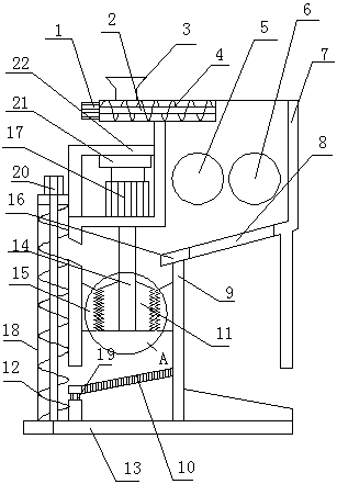
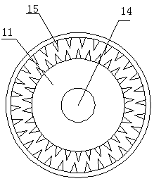
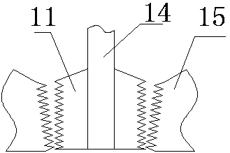
[0017] Such as Figure 1~3 As shown, a circulating crushing device with adjustable particle size includes a machine body 7, a feeding cylinder, an active crushing roller 6 and a driven crushing roller 5. A crushing cavity is arranged inside the body 7, and an inlet There are active crushing roller 6 and driven crushing roller 5 in the crushing chamber below the feeding barrel, one end of the active crushing roller 6 is connected to the motor A through the reducer, and the active crushing roller 6 and the driven crushing roller 5 are meshed. A discharge port A is provided below the active crushing roller 6 and the driven crushing roller 5, and a filter screen 8 is provided at the upper end of the discharge port A, and the filter screen 8 is arranged obliquely;

[0018] A seco...


PUM


Abstract

The invention discloses an adjustable particle size circulation stone crushing device. The adjustable particle size circulation stone crushing device comprises a machine body, a feeding barrel, a driving crushing roller and a driven crushing roller. A crushing cavity is formed in the machine body. The feeding barrel is arranged at the top end of the machine body, and the part, below the feeding barrel, of the crushing cavity is internally provided with the driving crushing roller and the driven crushing roller. One end of the driving crushing roller is connected with a motor A through a speedreducer. A discharging port A is formed below the driving crushing roller and the driven crushing roller. A filter sieve is arranged at the upper end of the discharging port A. A supporting frame is arranged on the left side of the machine body and provided with a lifting device. A motor B is connected to the lower end of the lifting device. The output end of the motor B is connected with a rotation shaft through a connector. A crushing tooth disc is arranged on the rotation shaft, a fixing crushing tooth ring is fixed to the part, on the outer side of the crushing tooth disc, of the machine body, and the inner diameter of the fixing crushing tooth ring is in an inverted cone shape with the large upper part and the small lower part. A support is arranged below the crushing tooth disc, a vibration plate is arranged on the support, a spring is arranged between the vibration plate and the support, and an elevating device is arranged on one side of the vibration plate.

Description

technical field [0001] The invention relates to the field of stone crushing devices, in particular to a circulating stone crushing device with adjustable particle size. Background technique [0002] Mining machinery equipment refers to machinery specialized in mining, mineral processing, and prospecting. A large number of cranes, conveyors, fans and drainage machinery used in mining operations are collectively referred to as mining machinery and equipment. The crusher is a common mining equipment. The crusher mainly relies on the impact energy to complete the crushing operation. When the crusher is working, the motor drives the rotor to rotate at a high speed, and the material enters the crusher cavity evenly. The impact, shearing and tearing of the material cause the material to be broken. The crusher can break the ore into small particles, which is convenient for processing and transportation. Modern crushers have many defects. For example, modern crushing equipment can on...

Claims


Application Information

Patent Timeline
Patent Type & Authority Applications(China)
IPC IPC(8): B02C4/02B02C2/10B02C23/12B02C23/14B02C23/02
CPCB02C4/02B02C2/10B02C23/02B02C23/12B02C23/14
Inventor 张阳张强周磊胡海前
Owner 成都人人揭网络科技有限公司
Learn More