Substrate turnover tray

A technology for carrying discs and substrates, which is applied in the fields of instruments, nonlinear optics, optics, etc., and can solve problems such as substrate fragments and hindering the normal taking of substrates

Active Publication Date: 2020-10-30
WUHAN CHINA STAR OPTOELECTRONICS TECH CO LTD
View PDF7 Cites 0 Cited by
  • Summary
  • Abstract
  • Description
  • Claims
  • Application Information

AI Technical Summary

Problems solved by technology

like figure 1 As shown, an existing substrate turnover tray includes: a plurality of trays 100 arranged in an array, on the bottom surface of the tray 100 is formed a carrying boss 101, and the surroundings of the carrying boss 101 are formed There are communication grooves 102, a plurality of first grooves 103 are formed on the carrying boss 101, and second grooves 104 are formed on the side wall 105 of the carrying plate 100, wherein the carrying boss 101 is used to carry the substrate, The first groove 103 is used to reduce the contact area between the substrate and the carrying boss 101 to prevent the substrate from being scratched, and the second groove 104 and the communication groove 102 are used to provide a force application position for the operator to facilitate taking and placing the glass substrate, such as figure 1 As shown, in the existing substrate turnover tray, the first groove 103 is independently formed on the carrying boss 101, and when the substrate is placed on the carrying boss 101, the first groove 103 is completely covered to form a closed space , there is no ventilation channel with the external environment, it is easy to generate vacuum adsorption, which hinders the normal handling of the substrate, especially when there is water vapor attached to the substrate, the water vapor fills the contact surface between the substrate and the carrying boss 101, and the probability of vacuum adsorption occurs Higher, if the film is forcibly removed after vacuum adsorption, it is likely to cause the substrate to break

Method used


Image

  • Substrate turnover tray
  • Substrate turnover tray
  • Substrate turnover tray

Examples


Embodiment Construction

[0025] In order to further illustrate the technical means adopted by the present invention and its effects, the following describes in detail in conjunction with preferred embodiments of the present invention and accompanying drawings.

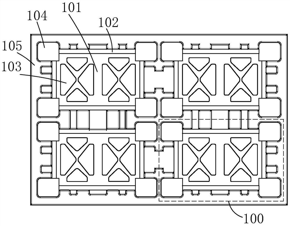
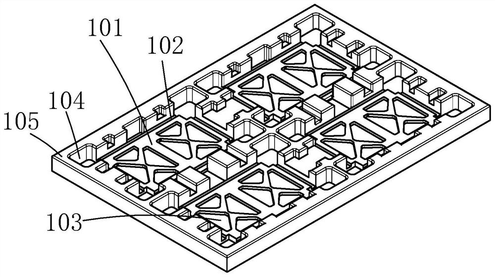
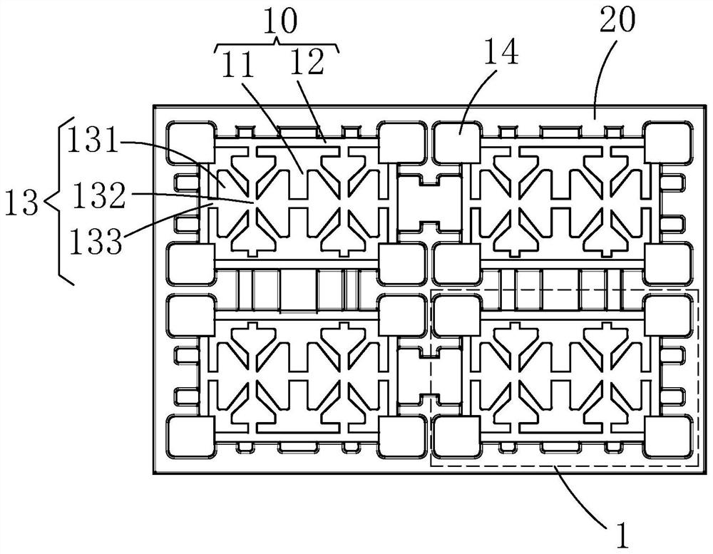
[0026] see image 3 , the present invention provides a substrate turnover tray, comprising: at least one tray 1, each tray 1 includes: a bottom surface 10 and a side wall 20 connected to the bottom surface 10 and surrounding the bottom surface 10; the bottom surface 10 includes: a bearing boss 11 and a communication groove 12 extending around the bearing boss 11, a first groove 13 is formed in the bearing boss 11, a second groove 14 is formed in the side wall 20, The concave direction of the communication groove 12 , the first groove 13 and the second groove 14 is perpendicular to the bottom surface 10 , and the first groove 13 and the second groove 14 are all in communication with the communication groove 12 .

[0027] Specifically, in some ...


PUM


Abstract

The invention provides a substrate transfer tray. The substrate transfer tray comprises at least one carrying plate, wherein each carrying plate comprises a bottom surface and side walls connected with the bottom surface and surrounding the bottom surface; each bottom surface comprises a carrying boss and a communicating groove extending along the periphery of the carrying boss, a first groove isformed in the carrying boss, second grooves are formed in the side walls, the sinking direction of the communicating groove, the first groove and the second grooves is perpendicular to the bottom surface, and the first groove and the second grooves are communicated with the communicating groove. The first grooves formed in the carrying bosses are communicated with the communicating grooves, so that vacuum adsorption of substrates by the tray can be prevented, the sheet breakage rate can be reduced, the sheet taking speed can be increased, and the production efficiency can be improved.

Description

technical field [0001] The invention relates to the technical field of display manufacturing, in particular to a substrate turnover carrier. Background technique [0002] With the development of display technology, liquid crystal displays (Liquid Crystal Display, LCD) and other flat display devices are widely used in mobile phones, televisions, personal Various consumer electronic products such as digital assistants, digital cameras, notebook computers, and desktop computers have become the mainstream of display devices. [0003] Most of the liquid crystal display devices currently on the market are backlight liquid crystal displays, which include a liquid crystal display panel and a backlight module (Backlight Module). The working principle of the liquid crystal display panel is to place liquid crystal molecules between two parallel glass substrates. There are many vertical and horizontal small wires between the two glass substrates. The direction of the liquid crystal mol...

Claims


Application Information

Patent Timeline
Patent Type & Authority Patents(China)
IPC IPC(8): G02F1/13
CPCG02F1/1303
Inventor 张夏黄建龙郑绍谷
Owner WUHAN CHINA STAR OPTOELECTRONICS TECH CO LTD
Why Eureka
Try Eureka