Underground utility tunnel structure with rainwater and sewage inflow function

A technology that integrates pipe gallery and rainwater and sewage, which is used in underwater structures, sewage removal, infrastructure engineering, etc.

Inactive Publication Date: 2018-09-25
SHENYANG JIANZHU UNIVERSITY
View PDF0 Cites 4 Cited by
  • Summary
  • Abstract
  • Description
  • Claims
  • Application Information

AI Technical Summary

Problems solved by technology

If it is connected with the rainwater pipeline or the discharge outlet of the downstream section that has not implemented the comprehensive pipeline gallery, there will be certain problems in the elevation

Method used


Image

  • Underground utility tunnel structure with rainwater and sewage inflow function
  • Underground utility tunnel structure with rainwater and sewage inflow function

Examples


Embodiment 1

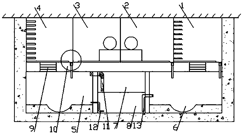
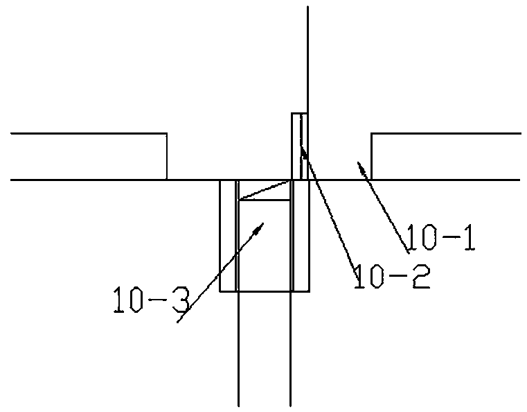
[0015] Embodiment 1: as Figure 1-2 Shown: an underground comprehensive pipe gallery structure with rain and sewage inflow, including cable cabin 1, water supply cabin 2, gas cabin 3, communication cabin 4, rainwater cabin 5, sewage cabin 6, water storage cabin 7, preliminary purification of sewage Cabin 8, inspection hole 9, drainage communication system 10, control water pipe 11, water guide pipe 12, water filter pipe 13; cable cabin 1, water supply cabin 2, gas cabin 3, and communication cabin 4 are respectively located in a kind of underground with rainwater inflow The upper part of the integrated pipe gallery structure, in which the cable cabin 1 and the communication cabin 4 correspond to the sewage cabin 6 and the rainwater cabin 5 in the lower part of the underground comprehensive pipeline structure with rainwater inflow, and the sewage cabin 6 and rainwater cabin 5 are respectively Located on both sides of the lower part of an underground comprehensive pipe gallery st...


PUM


Abstract

The invention relates to an underground utility tunnel structure, in particular to an underground utility tunnel structure with the rainwater and sewage inflow function. The underground utility tunnelstructure comprises a cable tank, a water supply tank, a gas tank, a communication tank, a rainwater tank, a sewage tank, a water storage tank, a sewage preliminary purification tank, manholes, a drainage communication system, a control water pipe, a water guide pipe and a water filter pipe, wherein the cable tank, the water supply tank, the gas tank and the communication tank are located at theupper-layer part of the underground utility tunnel structure with the rainwater and sewage inflow function, and the sewage tank and the rainwater tank are located on the two sides of the lower-layer part of the underground utility tunnel structure. According to the underground utility tunnel structure, the rainwater tank and the sewage tank are arranged in a utility tunnel, in addition, the waterstorage tank and the sewage primary purification tank are additionally arranged in consideration of the functions of water storage and water purification, so that a closed water collection, treatmentand storage integrated system is formed, and the manholes are formed in the utility tunnel, so that the problem that rainwater and sewage pipes are difficult to overhaul and inspect can be solved; andthe utility tunnel achieves the functions of regulation, storage and purification of a water body, and the function of a sponge city can be conveniently achieved.

Description

technical field [0001] The invention relates to an underground pipe gallery structure, in particular to an underground comprehensive pipe gallery structure with inflow of rainwater and sewage. Background technique [0002] The comprehensive pipe gallery is a box culvert tunnel built underground to accommodate two or more types of municipal pipelines. At present, there are technical difficulties in incorporating rainwater and sewage into it. Since the comprehensive pipe gallery has a certain height, the rainwater pipes are installed at the bottom of the comprehensive pipe gallery, and there is significant rainwater drop. If it is connected with the rainwater pipeline in the downstream section where the integrated pipeline gallery is not implemented or with the discharge outlet, there will be certain problems in the elevation. The sponge city puts forward requirements for urban waterlogging prevention and rainwater resources, and hopes to use the inner space of the pipe galle...

Claims


Application Information

Patent Timeline
Patent Type & Authority Applications(China)
IPC IPC(8): E02D29/045E03F1/00
CPCE02D29/045E03F1/003
Inventor 张延年马向楠
Owner SHENYANG JIANZHU UNIVERSITY
Why Eureka
Try Eureka