
Liquid extractor for high-pressure radiography injector

A technology for syringes and liquid pumps, which is applied in the field of liquid pumps for high-pressure radiography syringes, which can solve the problems of long liquid pumping time, viscous contrast medium, troublesome operation, etc., shorten the pumping time, reduce work intensity, and facilitate operation Effect

Inactive Publication Date: 2018-09-25
迈德旺(苏州)医疗设备有限公司
View PDF6 Cites 4 Cited by
  • Summary
  • Abstract
  • Description
  • Claims
  • Application Information

AI Technical Summary

Problems solved by technology

[0002] Clinically, during the treatment of cardiovascular diseases, such as coronary angiography and left heart angiography for the clinical treatment of congenital heart disease and rheumatic heart disease, when injecting contrast medium, in order to accurately understand the condition of the patient's blood vessels, it is necessary to inject the contrast medium Bolus injection into the blood vessel for imaging. At present, the pumping and injection of the existing contrast agent are all done on the CT imaging equipment. Each time the liquid is pumped, due to the viscosity of the contrast medium, the pumping time is long and the efficiency is low. The operation is very troublesome, time-consuming and labor-intensive, which brings great difficulty to the medical staff and increases the waiting time of the patient

Method used


Image

  • Liquid extractor for high-pressure radiography injector
  • Liquid extractor for high-pressure radiography injector
  • Liquid extractor for high-pressure radiography injector

Examples


Embodiment Construction

[0014] The present invention will be described in further detail below in conjunction with the accompanying drawings.

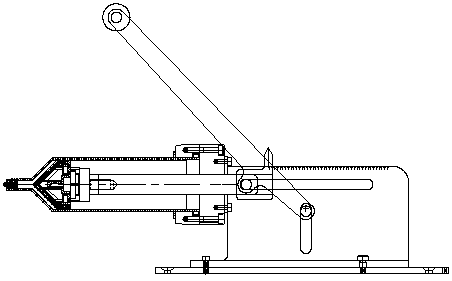
[0015] refer to Figure 1 to Figure 3 , a liquid pump for a high-pressure radiography syringe, comprising a high-pressure radiography syringe barrel 3, a piston 2 disposed in the high-pressure radiography syringe barrel 3, a syringe mounting and fixing seat 4, a connecting part 5, a frame 13, and a frame fixing seat 1 and a push rod 7, the syringe installation and fixing seat 4 is fixedly sleeved on the tail end of the high-pressure radiography syringe 3, and the high-pressure radiography syringe 3 is installed and fixed on the frame through the syringe installation and fixing seat 4 and the connecting part 5 On the left side of 13, a slide rail one 6 is horizontally arranged above the front side of the frame 13, and a slide rail two 10 is vertically vertically provided on the frame 13 below the slide rail one 6, and the push rod 7 One end of the piston 2 is...


PUM


Abstract

The invention belongs to the field of medical equipment and apparatuses, and particularly relates to a liquid extractor for a high-pressure radiography injector. The liquid extractor comprises a high-pressure radiography injector needle cylinder, a piston arranged in the high-pressure radiography injector needle cylinder, an injector installation fixing seat, a connecting component, a rack, a rackfixing seat and a pushing rod, the injector installation fixing seat fixedly sleeves the tail end of the high-pressure radiography injector needle cylinder, and the high-pressure radiography injectorneedle cylinder is installed at and fixed to the left side of the rack through the injector installation fixing seat and the connecting component; a first sliding rail is transversely and horizontally arranged above the front side face of the rack, a sliding rail is longitudinally and vertically arranged on the position, below the first sliding rail, of the rack, one end of the pushing rod is inclamping connection with the piston mutually and cooperatively, and the other end of the pushing rod is fixed to the middle of the connecting rod through a first pin column. Through the structure design of the liquid extractor, a handle can be rotated manually to complete the liquid extracting operation, the efficiency of the liquid extracting operation is ensured, working intensity of medical workers is reduced, and the operation is convenient, safe and reliable.

Description

technical field [0001] The invention belongs to the field of medical equipment, and in particular relates to a liquid pump for a high-pressure radiography syringe. Background technique [0002] Clinically, during the treatment of cardiovascular diseases, such as coronary angiography and left heart angiography for the clinical treatment of congenital heart disease and rheumatic heart disease, when injecting contrast medium, in order to accurately understand the condition of the patient's blood vessels, it is necessary to inject the contrast medium Bolus injection into the blood vessel for imaging. At present, the pumping and injection of the existing contrast agent are all done on the CT imaging equipment. Each time the liquid is pumped, due to the viscosity of the contrast medium, the pumping time is long and the efficiency is low. The operation is very troublesome, time-consuming and labor-intensive, which brings great work difficulty to medical staff and increases the wait...

Claims


Application Information

Patent Timeline
Patent Type & Authority Applications(China)
IPC IPC(8): A61M5/00A61M5/20A61M5/31
CPCA61M5/007A61M5/008A61M5/20A61M5/31A61M2005/2006
Inventor 徐晨元金雄帅黄煜
Owner 迈德旺(苏州)医疗设备有限公司
Learn More