


Quick Research
Generate reliable direction feasibility study reports for your R&D in just a few steps.

Technical Q&A
Discover and master advanced knowledge NOW. Basics, ideas, possibilities, all at once.

Find Solutions
As an expert in R&D theories, this can generate solutions to your technical problems instantly.

Evaluate Feasibility
Analyze your overall solution with one click, know your potential R&D risks in advance.

Monitor Landscape
Get weekly tech updates, stay abreast of the latest tech innovations and key insights.
Battery pack terminal structure and dust collector
A terminal structure and battery pack technology, which is applied in the installation of vacuum cleaners, electrical equipment, cleaning equipment, etc., can solve the problems of complex processing and inconvenient charging, and achieve the effect of simple processing and convenient use
- Summary
- Abstract
- Description
- Claims
- Application Information
AI Technical Summary
Problems solved by technology
Method used
Image

Examples
Embodiment 1
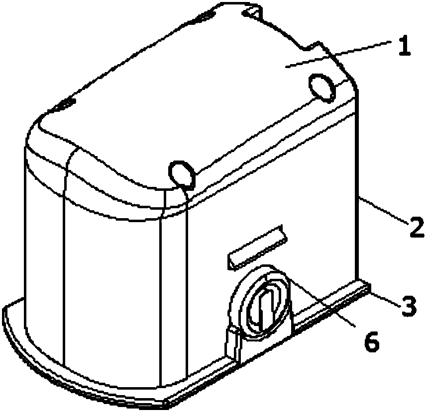
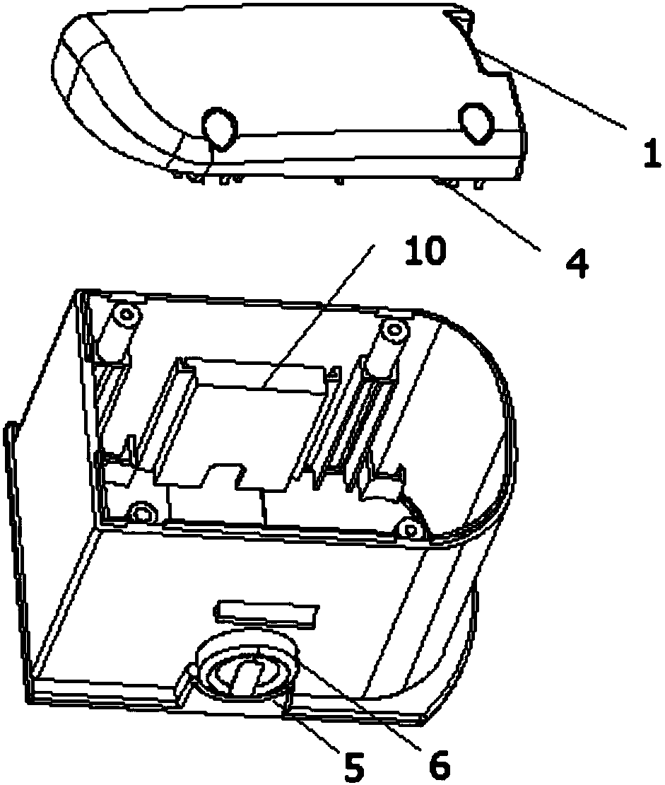
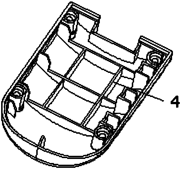
[0058] figure 1 A schematic diagram of the external structure of the battery pack shell structure provided by Embodiment 1 of the present invention; figure 2 An exploded view of the battery pack case structure provided in Embodiment 1 of the present invention; image 3 It is a schematic diagram of the structure of the upper cover in the case structure of the battery pack provided by Embodiment 1 of the present invention.
[0059] Such as Figure 1 to Figure 3 As shown, the battery pack casing structure provided by the first aspect of the present invention includes an upper cover 1, an intermediate case 2 and a lower cover 3, and a battery pack 8 is formed between the intermediate case 2 and the lower cover 3. cavity, the upper cover 1 is provided with reinforcing ribs 4 corresponding to the battery pack 8 , and the middle case 2 is provided with an unlock button 6 .
[0060] In the case structure of the battery pack provided by the present invention, the upper cover 1 is p...
Embodiment 2
[0077] Such as Figure 8 As shown, the present invention provides a battery structure, which includes an upper cover 1, an intermediate case 2, a lower cover 3 and a battery pack 8, and a battery is formed between the intermediate case 2 and the lower cover 3 for placing the battery. The cavity of the battery pack 8, the side of the battery pack 8 is provided with a chip 15, and the middle case 2 is provided with an unlock button 6.
[0078] In any of the above technical solutions, further, the battery pack 8 is provided with a clip 7, the side of the clip 7 is provided with a protrusion 18, and the chip 15 is provided with a Matching card holes.
[0079] In any of the above technical solutions, further, the intermediate housing 2 is provided with a through hole, and the unlock button 6 is penetrated through the through hole.
[0080] In any of the above technical solutions, further, the through hole includes a first through hole 26, the unlocking button 6 is provided with a...
Embodiment 3
[0088] The present invention also provides an overall structure of a battery pack, which includes a battery pack 8, a clamping member 7 and a chip 15, the clamping member 7 is provided with a receiving groove 19, and the battery pack 8 is located in the receiving groove Inside 19 , a protrusion 18 is provided on the side of the clip 7 , a card hole matching the protrusion 18 is provided on the chip 15 , and a terminal 16 is provided on the chip 15 .
[0089] In any of the above technical solutions, further, the clip 7 includes a first clip 22 and a second clip 23, the first clip 22 is arranged on the top of the battery pack 8, so The second clamping member 23 is disposed at the bottom of the battery pack 8 .
[0090] In any of the above technical solutions, further, the first clamping member 22 and the second clamping member 23 are clamped by a clamping column.
[0091] In any of the above technical solutions, further, the clamping post of the second clamping member 23 is pro...
PUM
 Abstract
Description
Claims
Application Information
 - R&D Engineer
- R&D Manager
- IP Professional
- Industry Leading Data Capabilities
- Powerful AI technology
- Patent DNA Extraction
Browse by: Latest US Patents, China's latest patents, Technical Efficacy Thesaurus, Application Domain, Technology Topic, Popular Technical Reports.
© 2024 PatSnap. All rights reserved.Legal|Privacy policy|Modern Slavery Act Transparency Statement|Sitemap|About US| Contact US: help@patsnap.com