
Stray current acquiring method and stray current detection system

A stray current and detection device technology, applied in the field of rail transit, can solve the problems of potential safety hazards, difficulty in estimating buried metal corrosion, and inability to directly calculate the value of stray current, so as to reduce errors and improve reliability Effect

Active Publication Date: 2018-09-21
STATE GRID HUNAN ELECTRIC POWER +2
View PDF10 Cites 16 Cited by
  • Summary
  • Abstract
  • Description
  • Claims
  • Application Information

AI Technical Summary

Problems solved by technology

Therefore, the existing polarization potential monitoring method that reflects the distribution of stray currents cannot know the specific value of the distribution of stray currents in the interval, and it is difficult to estimate the corrosion of buried metals that have been at critical dangerous voltages for a long time, and there are potential safety hazards; at the same time, due to The polarization potential is the offset obtained from different reference electrodes, and it is difficult to establish a direct numerical relationship with the corrosion characteristic quantity and the DC bias magnetic characteristic quantity of the transformer due to its diversity.
[0004] To sum up, the impact of subway stray currents on buried metal corrosion and surrounding power grids is increasing day by day, and the existing technology can only indirectly reflect the distribution of stray currents, and cannot directly calculate the value of stray currents, resulting in the inability to timely and effectively Realize the protection and monitoring of stray current

Method used


Image

  • Stray current acquiring method and stray current detection system
  • Stray current acquiring method and stray current detection system
  • Stray current acquiring method and stray current detection system

Examples


Embodiment Construction

[0091] The present invention will be further described below in conjunction with examples.

[0092] The content of the present invention will be further described and explained below in conjunction with the accompanying drawings. like Figure 13 As shown, a stray current acquisition method provided by the present invention includes the following steps:

[0093] Step 1: Collect the detection data of each stray current detection device in the power supply section of the train traction substation.

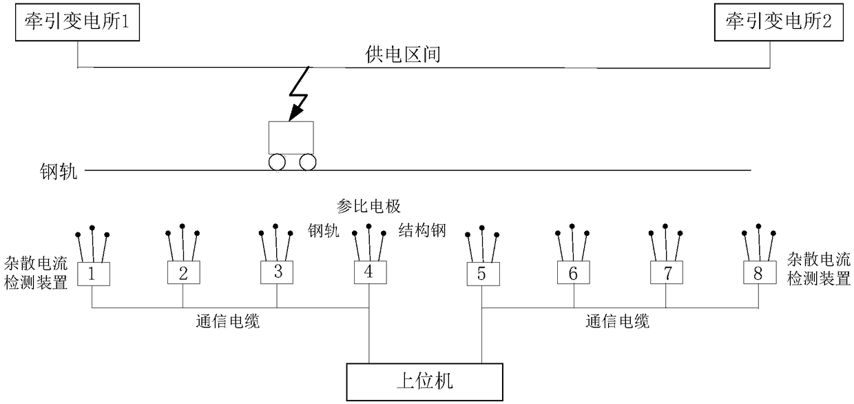
[0094] like figure 1As shown, stray current detection devices are installed in the power supply interval of the two traction substations of the subway. The number of stray current detection devices depends on the length of the interval. For example, if 6 or 8 are set, each stray current detection device is connected through a communication cable, and the detection data (natural body potential, reference potential, rail potential) is transmitted to The upper computer records and ca...


PUM


Abstract

The invention discloses a stray current acquiring method and a stray current detection system. The acquiring method comprises the following steps: (1) collecting detection data of each stray current detection device; (2) calculating a polarization potential of the stray current detection device, and carrying out normalization processing, so as to obtain a reduced polarization potential; (3) calculating a track potential of the stray current detection device, and calculating a track current of the stray current detection device; (4) acquiring a traction current of a current train, and calculating a stray current of the stray current detection device; (5) acquiring a running environment of the current train, and constructing fitting data sets; and (6) carrying out one-dimensional polynomialcurve fitting on the data in each fitting data set, so as to obtain a distribution function of the stray current. According to the stray current acquiring method, a manner for acquiring the stray current in a power supply interval at the moment is provided, and a specific numerical value can be acquired, so that the stray current can be relatively timely and effectively monitored.

Description

technical field [0001] The invention belongs to the technical field of rail transit, and in particular relates to a stray current acquisition method and a stray current detection system. Background technique [0002] Urban rail transit plays a huge economic and social role in solving traffic problems in large and medium cities. However, while rail transit brings convenience to people's lives, there are also some problems that cannot be ignored. Because the subway rails are difficult to completely insulate the earth, part of the current leaks to the ground through the rails. This part of the current is called Stray current or stray current. Stray currents will be distributed in various areas where the subway lines extend. Stray currents will not only cause serious electrochemical corrosion to metal components and buildings underground or on the ground in the urban rail system (1A stray currents will cause metal weight loss of up to 9.13kg), for example, in Hong Kong, gas pi...

Claims


Application Information

Patent Timeline
Patent Type & Authority Applications(China)
IPC IPC(8): G01R19/00
CPCG01R19/00
Inventor 彭平周卫华曾祥君喻锟倪砚茹冷阳刘赟刘味果
Owner STATE GRID HUNAN ELECTRIC POWER
Learn More