T-pipe bulging forming device and bulging forming method for branch pipe of T-pipe

A three-way tube and bulging technology, which is applied in the field of three-way tube bulging forming devices, can solve the problems of poor uniformity of wall thickness at the forming part, high control accuracy and difficulty in operation, large deformation of local bulges, etc. Convenience and reliability, increased efficiency and synergistic continuity, less breakable effect

Inactive Publication Date: 2018-09-21
NANCHANG HANGKONG UNIVERSITY
View PDF7 Cites 10 Cited by
  • Summary
  • Abstract
  • Description
  • Claims
  • Application Information

AI Technical Summary

Problems solved by technology

The current three-inflation bulging process has the following defects: 1. Since the pressure of the lower jacking cylinder is constant during the forming process, if the forming pressure of the lower jacking cylinder is high during the forming process, the flow of material to the raised branch cavity will be slowed down. , affecting the bulging height
In the later period, if the pressure value of the lower jacking cylinder is small and the support pressure is not enough, the raised branch pipe will be broken; 2. When the lower jacking cylinder supports the branch pipe under constant pressure to bulge, the material of the formed branch pipe is always in a state of expanding outward from the cavity; It has been in the process of thinning and deformation from the beginning, so the difficulty of forming with constant support force lies in the large deformation of local bulges. Different materials have different forming difficulties. The low bulging height has always been a problem that plagues its forming, and the thinning is serious. Poor thickness uniformity, severe work hardening, poor product quality stability, high control accuracy and difficult operation

Method used


Image

  • T-pipe bulging forming device and bulging forming method for branch pipe of T-pipe
  • T-pipe bulging forming device and bulging forming method for branch pipe of T-pipe
  • T-pipe bulging forming device and bulging forming method for branch pipe of T-pipe

Examples


Embodiment Construction

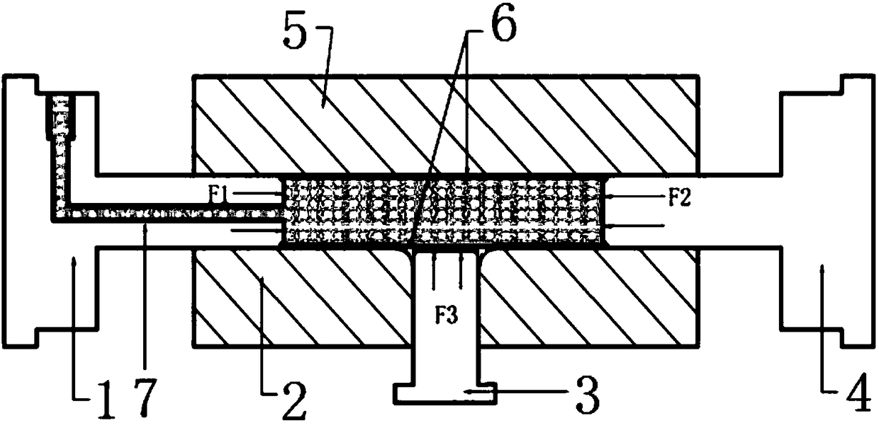
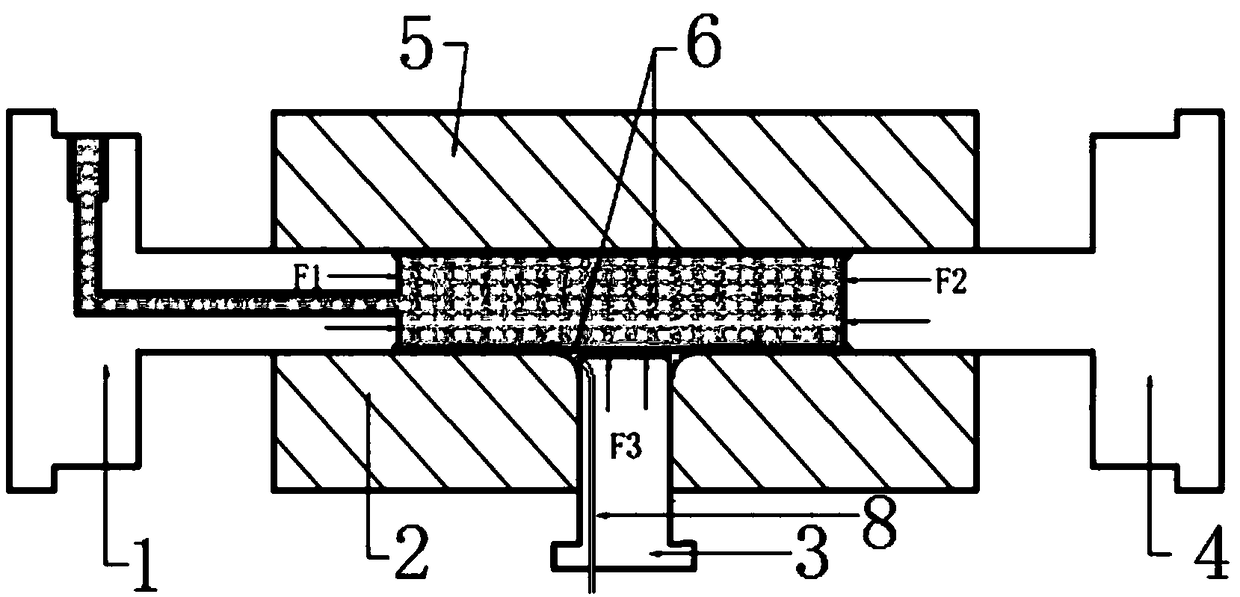
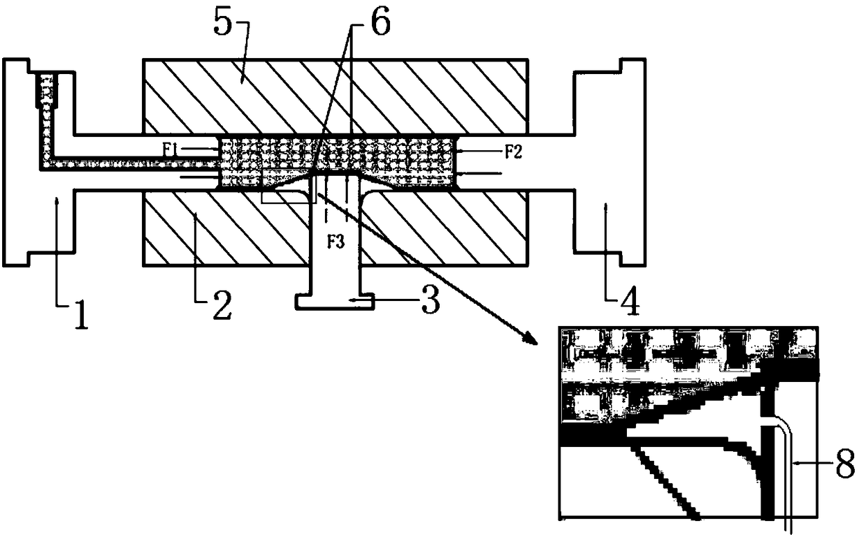
[0028] The specific embodiments of the present invention will be further described below in conjunction with the accompanying drawings.

[0029] like Figure 1-4 As shown, the present invention is realized in such a way that the three-way pipe bulging forming device at least includes a mold, a pressure medium injection device, a pressure pushing head device, a cylinder jacking device, a pressure sensor, a displacement sensor and a controller, wherein the pressure medium The injection device is used to inject pressure medium into the tube blank 6 in the mold cavity; the pressure pusher device is used to squeeze the end of the tube blank and the pressure medium, and the pressure medium generates pressure to make the tube blank 6 expand and form; the jacking device and The bulging part of the branch pipe on the tube blank 6 contacts and exerts force during the bulging and forming of the branch pipe; the pressure sensor is used to detect the pressure of the pressure medium; the di...


PUM


Abstract

The invention provides a T-pipe bulging forming device and a forming method. The T-pipe bulging forming device at least comprises a mold, a pressure medium injection device, a pressure push head device, a pressure sensor, a displacement sensor and a controller, wherein the controller is electrically connected with the pressure sensor and the displacement sensor, and is also in control connection with the pressure push head device, a top cylinder device and a power module of the pressure medium injection device. On the one hand, improved design is performed on the structure of the T-pipe bulging forming device, so that the working efficiency and the cooperative continuity are effectively improved while requirements on the operation convenience and reliability are satisfied. The pressures and displacements of a pressure medium, a push head and a top cylinder are monitored and adjusted in real time. On the other hand, a T-pipe bulging forming process is improved, and a method that outwardbulging is performed on a forming part material of a branch pipe after in-pipe pre-stretching bulging is adopted, so that the thickness uniformity of the bulged wall of the branch pipe can be remarkably improved, the probability of fracture is low, and the limit bulging height of the branch pipe is effectively increased.

Description

technical field [0001] The invention relates to the technical field of tee pipe bulge forming, in particular to a tee pipe bulge forming device and a tee branch pipe bulge forming method. Background technique [0002] The bulging of the tee pipe is to realize the forming of the pipe by pressurizing the inside of the pipe and feeding material in the axial direction. In actual production, it is always hoped that the limit branch height of the tee pipe should be as high as possible, so as to reduce the subsequent welding process of the part branch, improve production efficiency and reduce costs. [0003] In the traditional three-way expansion, the lower jacking cylinder acts as a support for the raised branch pipe, and is passively retreated in the raised direction. Generally, the jacking cylinder works with constant pressure. The current three-inflation bulging process has the following defects: 1. Since the pressure of the lower jacking cylinder is constant during the formin...

Claims


Application Information

Patent Timeline
Patent Type & Authority Applications(China)
IPC IPC(8): B21D26/037B21D26/043
CPCB21D26/037B21D26/043
Inventor 徐雪峰吴孔炜吴义旺肖洁付春林
Owner NANCHANG HANGKONG UNIVERSITY
Why Eureka
Try Eureka