
Electric heating smoking device with heat distribution function

A technology of dispensing function and smoking device, which is applied in the directions of smoker's products, tobacco, and application, can solve the problems of poor smoking feeling, easy curing, uneven heating of electric heating cigarettes, etc., so as to reduce the difficulty of production and prevent excessive temperature. high effect

Pending Publication Date: 2018-09-21
CHINA TOBACCO YUNNAN IND
View PDF0 Cites 1 Cited by
  • Summary
  • Abstract
  • Description
  • Claims
  • Application Information

AI Technical Summary

Problems solved by technology

[0005] The invention relates to an electric heating smoking device with heat distribution function, which effectively solves the problems of uneven heating, easy to burn, insufficient aroma components and poor smoking feeling of electric heating cigarettes

Method used


Image

  • Electric heating smoking device with heat distribution function
  • Electric heating smoking device with heat distribution function
  • Electric heating smoking device with heat distribution function

Examples


Embodiment 1

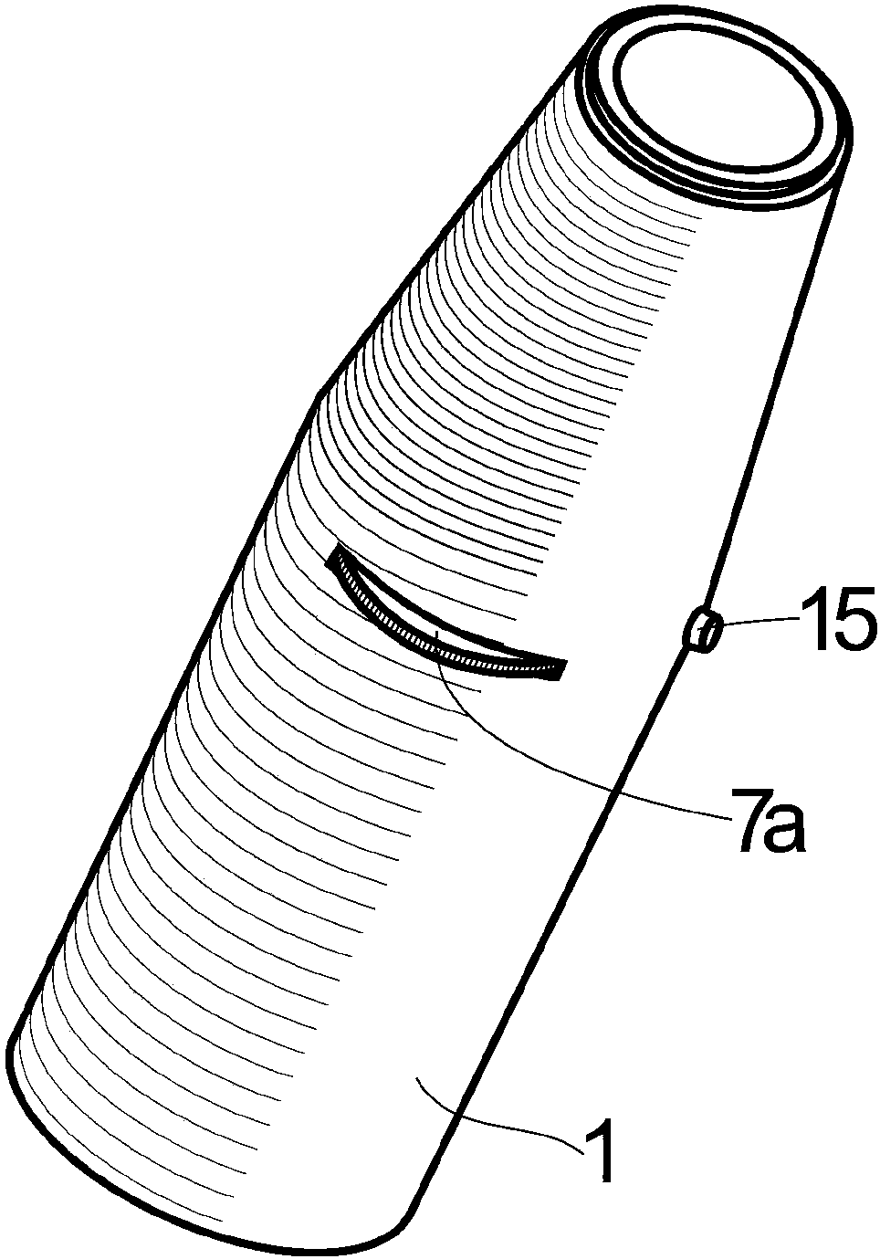
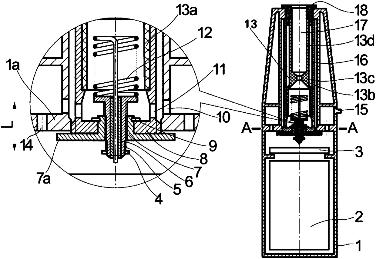
[0041] An electric heating smoking device with heat distribution function, which includes the following components:

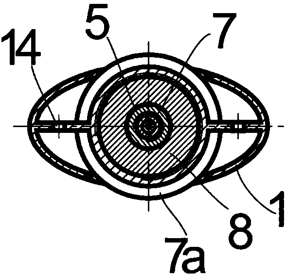
[0042] The shell 1 has an air intake hole on it, and it includes a rib plate 1a, and the rib plate 1a is provided with a first ventilation hole 14;

[0043] Insulation pipe 16, which is located in the shell 1, has a third vent hole 11 on its side wall, and the heat insulation pipe 16 is detachably installed on the heat insulation pipe base 8 with a cavity. The pipe base 8 is detachably installed on the rib plate 1a;

[0044] Venturi tube type heat storage pipe 13, which is located in the cavity of the heat insulation pipe 16, and includes: a gas collecting pipe 13a and a preheating pipe 13d, and the gas collecting pipe 13a and the preheating pipe 13d pass through the heat storage body The straight heating throat 13b surrounded by 13c is air-connected and connected, the cavity of the preheating pipe 13d is the cigarette accommodating cavity 17, and the cavity o...

Embodiment 2

[0054] The difference between this embodiment and Embodiment 1 is that the height adjustment mechanism of the heating wire 12 is simplified, and the matching with the cigarette to be smoked is realized by selecting the size of the heat storage body 13c.

[0055] The working principle of this embodiment is the same as that of Embodiment 1.

Embodiment 3

[0057] The difference between this embodiment and Embodiment 1 is that: the venturi tube type heat storage tube has increased the horizontal hot throat 13e and the stopper 13f, by adding the horizontal hot throat and the stopper, the hot air heated by the heating wire can be avoided from directly It enters the straight heat throat to prevent the hot air from being too fast and the heat is too high to burn the shredded tobacco. On the other hand, it can better store more heat in the heat storage body and transfer it to the relatively low temperature preheating tube , to achieve full preheating of cigarettes.

[0058] The working principle of this embodiment is the same as that of Embodiment 1.


PUM


Abstract

The invention relates to an electric heating smoking device with a heat distribution function. The electric heating smoking device comprises a shell (1), a heat-insulation pipe (16), a Venturi pipe type heat storage pipe (13) and a nut (7). Gas inlet holes are formed in the shell (1); a third air hole (11) is formed in the heat-insulation pipe (16), the Venturi pipe type heat storage pipe (13) ispositioned in a cavity of the heat-insulation pipe (16), and the nut (7) is fixedly connected with a nut turntable (7a). The electric heating smoking device has the advantages that the electric heating smoking device is provided with the Venturi pipe type heat storage pipe, a part of hot air heated by heating coils can be gathered in a gas collecting pipe and a heat storage body, the hot air can be transmitted to a preheating pipe for preheating cigarettes in advance, accordingly, hot air distribution effects can be realized, tobacco shreds can be prevented from being burnt due to excessivelyhigh temperature of the hot air, and heat can be redistributed and utilized.

Description

technical field [0001] The invention belongs to the field of electronic cigarette smoking set products, and in particular relates to an electric heating smoking device with heat distribution function. Background technique [0002] Existing cigarettes are directly ignited, although it is simple and convenient, because the tobacco is directly heated and ignited, so a certain amount of tar, nicotine and other harmful components will be produced during the smoking process, which will have a certain impact on the health of the smoker. The existing low-temperature heating of cigarettes uses electric heating appliances, through which various forms of heating appliances such as electric heating tubes, needles or plates are in direct contact with cigarettes or shredded tobacco, and the cigarettes are heated at a temperature lower than the ignition point of cigarettes. The direct contact baking of sticks or shredded tobacco can volatilize the aroma components of tobacco and meet the s...

Claims


Application Information

Patent Timeline
Patent Type & Authority Applications(China)
IPC IPC(8): A24F47/00
CPCA24F47/00
Inventor 吴俊朱东来陈永宽李寿波韩熠杨继巩效伟张霞李廷华周卫玲
Owner CHINA TOBACCO YUNNAN IND
Learn More