
Implantable device, electric energy emission and receiving unit thereof and electric energy transmission device

A technology for transmitting units and implanted equipment, applied in battery circuit devices, circuit devices, electrical components, etc., can solve the problems of high cost and cumbersome process, and achieve the effect of improving efficiency and improving electromagnetic safety.

Inactive Publication Date: 2018-09-18
BEIHANG UNIV
View PDF4 Cites 4 Cited by
  • Summary
  • Abstract
  • Description
  • Claims
  • Application Information

AI Technical Summary

Problems solved by technology

This process is not only traumatic, but also costly and relatively cumbersome

Method used


Image

  • Implantable device, electric energy emission and receiving unit thereof and electric energy transmission device
  • Implantable device, electric energy emission and receiving unit thereof and electric energy transmission device
  • Implantable device, electric energy emission and receiving unit thereof and electric energy transmission device

Examples


Embodiment Construction

[0032] It should be noted that, in the case of no conflict, the implementation modes in the present application and the features in each implementation mode can be combined with each other.

[0033] Hereinafter, the present application will be described in detail with reference to the accompanying drawings and in combination with embodiments.

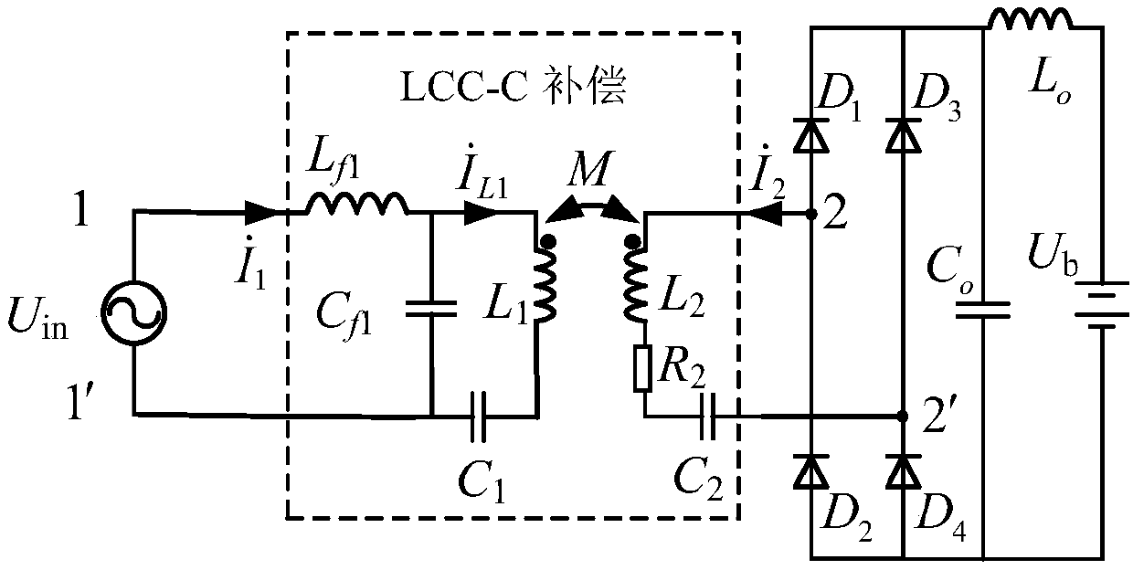
[0034] figure 1 The circuit model of the wireless power transmission device is shown. This model ignores the resistance of the transmitting coil but considers the resistance of the receiving coil, and only one capacitor is used for compensation at the receiving end. The circuit structure in the dotted line box can be called the LCC-C topology. exist figure 1 , the inductances of the receiving coil and the transmitting coil are L 1 and L 2 , ignoring the transmitting coil resistance, the receiving coil resistance is R 2 , the transmitter compensation capacitance is C 1 and C f1 , the compensation inductance is L f1 . Compensation...


PUM


Abstract

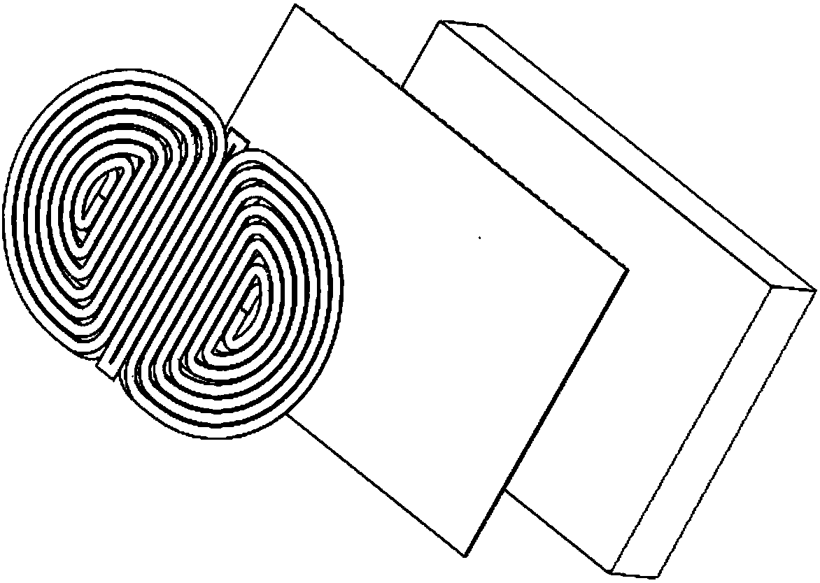
The invention discloses an implantable device, electric energy emission and receiving units thereof and an electric energy transmission device. The electric energy emission unit comprises a first ferrite film and an emission coil installed on the first ferrite film. The emission coil comprises a bipolarity coil with multiple coils. The electric energy receiving unit comprises a second first ferrite film and a receiving coil installed on the second ferrite film. The receiving coil comprises a bipolarity coil with multiple coils. According to the invention, bipolarity coils are used in the emission coil and the receiving coil, so compared with a unipolarity coil, through the parallel structure of the bipolarity coils, the wireless electric energy transmission efficiency is improved and the electromagnetic safety of a wireless electric energy transmission device is further improved.

Description

technical field [0001] The present invention relates to the field of wireless charging, in particular to an implantable device, an electric energy transmitting and receiving unit, and an electric energy transmission device. Background technique [0002] An increasing number of implantable devices are being developed in the current field of medical devices such as cardiac pacemakers, brain pacemakers, etc. [0003] Typically, implantable devices contain their own disposable batteries. When the battery is about to run out after a period of use, the implantable device needs to be taken out and re-implanted into the human body. This process is not only traumatic, but also costly and relatively cumbersome. Therefore, how to realize wireless energy supply to implantable devices has become a technical problem to be solved in this field. Contents of the invention [0004] In view of this, the present application proposes an implantable device, its power transmitting and receivi...

Claims


Application Information

Patent Timeline
IPC IPC(8): H02J7/02H02J50/12H01F38/14H01F27/28
CPCH01F27/28H01F38/14H02J7/02H02J50/12H02J50/005
Inventor 肖春燕程丁宁
Owner BEIHANG UNIV
Learn More