
Adjustable microstrip band-pass filter with adjustable center frequency and unchanged absolute bandwidth

A band-pass filter and center frequency technology, applied in the field of two-port microwave devices, can solve the problems of good frequency selection characteristics, increase filter insertion loss, size dependence, etc., achieve good frequency selection characteristics, improve out-of-band suppression characteristics, Overcome the effect of inconvenient debugging

Active Publication Date: 2018-09-18
SHANGHAI UNIV OF MEDICINE & HEALTH SCI
View PDF4 Cites 2 Cited by
  • Summary
  • Abstract
  • Description
  • Claims
  • Application Information

AI Technical Summary

Problems solved by technology

Traditional microstrip line comb filters, because microstrip line characteristics are difficult to achieve better frequency selection characteristics, usually need to increase the order of the filter to achieve high frequency selection characteristics, which not only increases the size of the filter, but also increases Insertion Loss of Filter
The waveguide filter has good frequency selection characteristics, but the size is heavily dependent on the frequency. The lower the frequency, the larger the size of the waveguide filter

Method used


Image

  • Adjustable microstrip band-pass filter with adjustable center frequency and unchanged absolute bandwidth
  • Adjustable microstrip band-pass filter with adjustable center frequency and unchanged absolute bandwidth
  • Adjustable microstrip band-pass filter with adjustable center frequency and unchanged absolute bandwidth

Examples


Embodiment

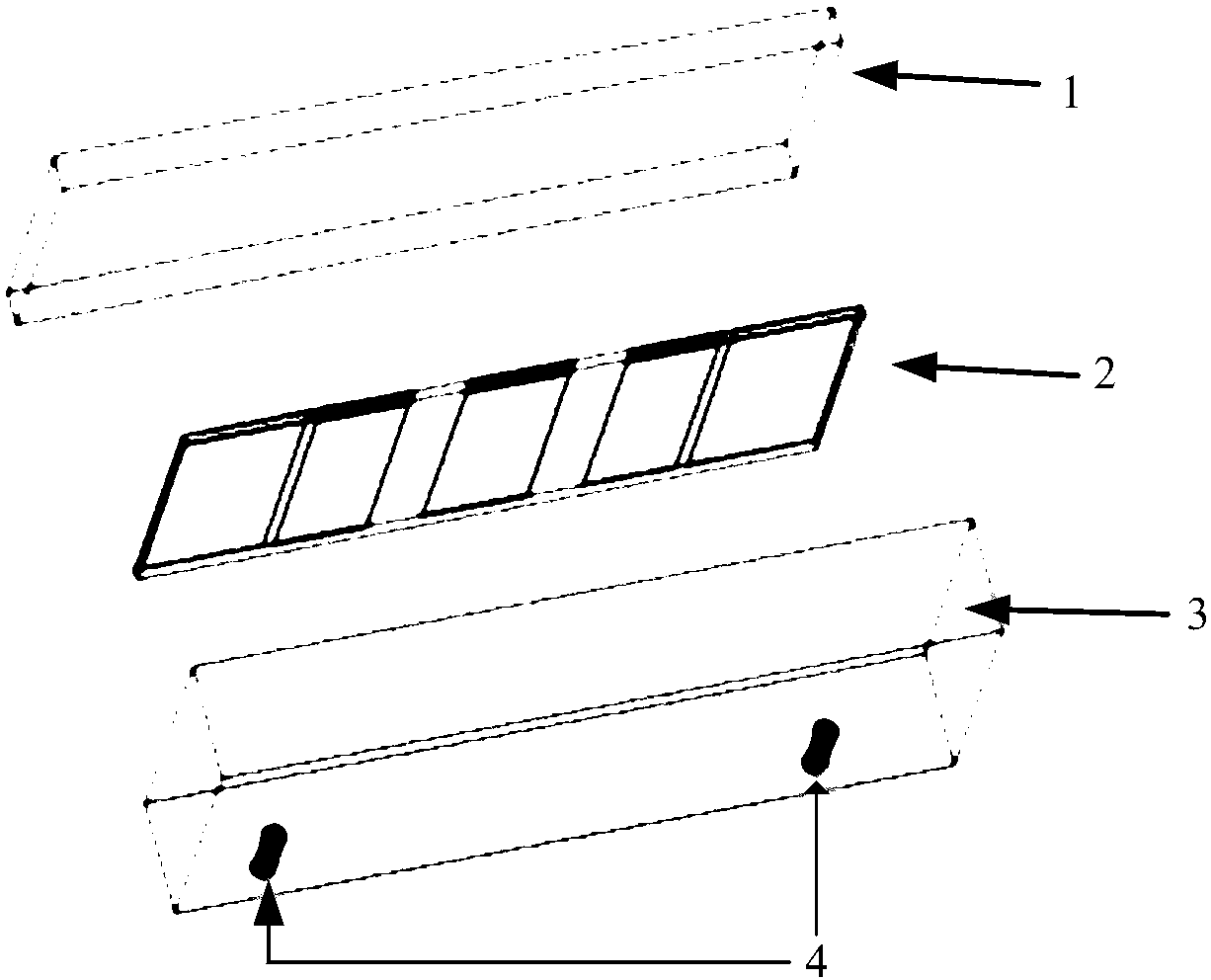
[0028] Such as figure 1 As shown, the metal rectangular cavity is a cuboid cavity, which is divided into cavity upper cover 1, microstrip line board 2 and cavity base 3 from top to bottom; SMA radio frequency interface 9 (SMA radio frequency interface: a specific type and size RF interface, also can be other models) as the signal input and output interface of the cavity filter, fixed on the cavity base by screws.

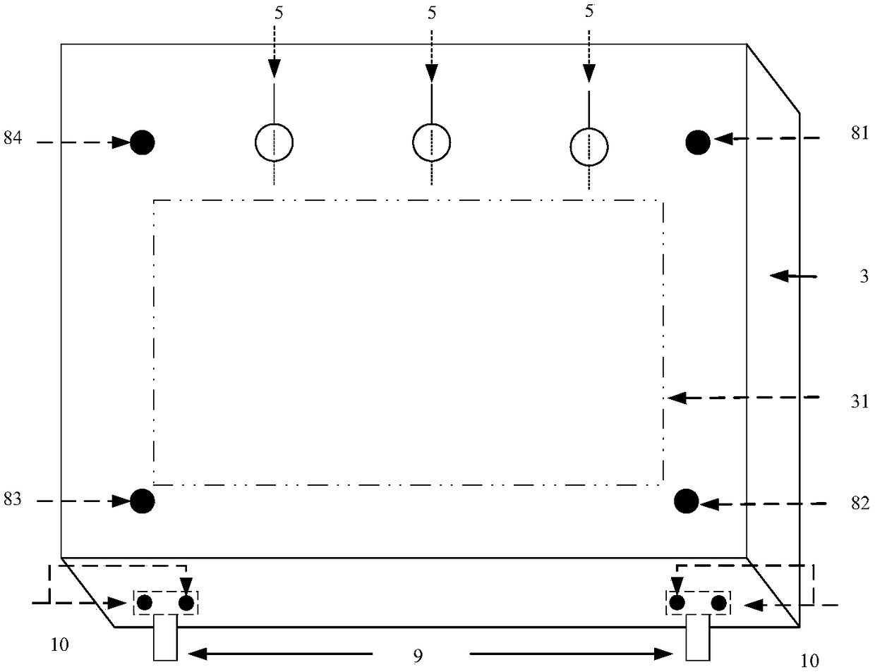
[0029] Such as figure 2 As shown, the upper cover 1 of the cavity and the base of the cavity 3 are fixed by four screws 81-84. The size of the screws is only suitable for the size of the current metal cavity. The purpose is to fix the cavity and form a closed metal cavity Environment; in the middle of the first fixed cavity screw 81 and the fourth fixed cavity screw 84, there are three core-through capacitor installation holes 5 for installing the core-through capacitor, and the through-core capacitor feeds power to the varactor inside the cavity Diode, the inter...


PUM

PropertyMeasurementUnit
Thicknessaaaaaaaaaa

Abstract

The invention relates to an adjustable microstrip band-pass filter with an adjustable center frequency and unchanged absolute bandwidth, and the filter comprises a metal rectangular cavity which comprises a cavity upper cover and a cavity pedestal, wherein the cavity upper cover and the cavity pedestal are fixedly connected through cavity fixing screws at four corners to form a resonant cavity. The cavity pedestal is provided with a cavity groove for realizing cavity resonance. The filter also comprises a microstrip line plate which is fixed inside the metal rectangular cavity through a cavityfixing screw, and is opposite to the cavity groove. The adjustment of the center frequency is achieved by a variable-capacity third-order LC resonant structure. Compared with the prior art, the filter has tunable center frequency, and facilitates the debugging.

Description

technical field [0001] The invention relates to a two-port microwave device, in particular to an adjustable microstrip band-pass filter with an adjustable center frequency and a constant absolute bandwidth. Background technique [0002] There are many ways to realize the microwave bandpass filter, such as microstrip line, waveguide, semi-lumped filter, and various filters have their own advantages and disadvantages. Traditional microstrip line comb filters, because microstrip line characteristics are difficult to achieve better frequency selection characteristics, usually need to increase the order of the filter to achieve high frequency selection characteristics, which not only increases the size of the filter, but also increases The insertion loss of the filter. The waveguide filter has good frequency selection characteristics, but the size is heavily dependent on the frequency. The lower the frequency, the larger the size of the waveguide filter. Contents of the invent...

Claims


Application Information

Patent Timeline
IPC IPC(8): H01P1/203
CPCH01P1/203Y02D30/70
Inventor 吴忠航邓杰
Owner SHANGHAI UNIV OF MEDICINE & HEALTH SCI
Learn More