A low-frequency flexible energy harvester and self-powered motion counter
An energy harvester and self-powered technology, applied in the field of micromechanical sensing, can solve the problems of low frequency power generation efficiency and unstable power supply of wearable energy harvesters, and achieve the effect of solving the loss of initial data and accurate counting results.
- Summary
- Abstract
- Description
- Claims
- Application Information
AI Technical Summary
Problems solved by technology
Method used
Image
Examples
Embodiment 1
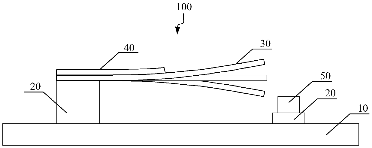
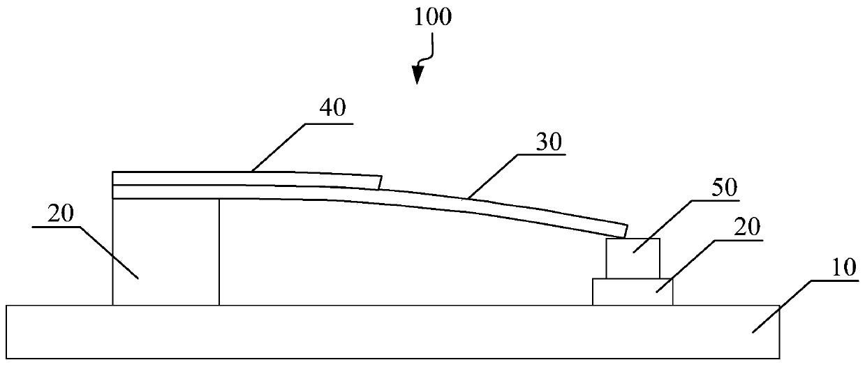
[0057] Such as figure 1 As shown, this embodiment provides a low-frequency flexible energy harvester, and the low-frequency flexible energy harvester 100 includes:
[0058] flexible substrate 10;
[0059] a support block 20, the support block 20 is located on the flexible substrate 10;
[0060] A cantilever beam 30, the first end of the cantilever beam 30 is fixed on the support block 20, and the second end of the cantilever beam 30 is a free end;
[0061] A piezoelectric thin film 40, the piezoelectric thin film 40 is located on the upper surface of the cantilever beam 30; and
[0062] A permanent magnet 50, the permanent magnet 50 is located on the flexible substrate 10 below the free end of the cantilever beam 30;
[0063] Wherein, a preset distance L is set between the free end of the cantilever beam 30 and the permanent magnet 50 .
[0064] As an example, such as figure 1 Said, the low-frequency energy harvester 100 further includes a support block 20 located between...
Embodiment 2
[0076] Such as Figure 5 As shown, this embodiment provides a low-frequency flexible energy harvester, and the low-frequency flexible energy harvester 100 includes:
[0077] flexible substrate 10;
[0078] a support block 20, the support block 20 is located on the flexible substrate 10;
[0079] A cantilever beam 30, the first end of the cantilever beam 30 is fixed on the support block 20, and the second end of the cantilever beam 30 is a free end;
[0080] a piezoelectric film 40, the piezoelectric film 40 is located on the upper surface of the cantilever beam 30; and
[0081] A first permanent magnet 51 and a second permanent magnet 52, the first permanent magnet 51 and the second permanent magnet 52 are respectively located on the flexible substrate 10 below the two corners of the free end of the cantilever beam 30;
[0082] Wherein, a first preset distance is set between the first permanent magnet 51 and the second permanent magnet 52, and the free end of the cantilever...
Embodiment 3
[0095] Such as Image 6 As shown, the present embodiment provides a self-powered motion counter comprising:
[0096] The low-frequency flexible energy harvester 100 as described in Embodiment 1 or Embodiment 2 is used as the power supply terminal of the self-powered motion counter, and generates and outputs counting signals based on body movements;
[0097] The adder 200 is connected with the low-frequency flexible energy harvester 100, and is used for receiving the counting signal sent by the low-frequency flexible energy harvester 100, and reading the existing counting information stored in the memory, and based on the existing step number information performing accumulative processing on said counting signal to realize self-powered motion counting;
[0098] A memory, connected to the adder, for storing the accumulation result output by the adder.
[0099] Since the deformation of the flexible substrate in the horizontal direction does not affect the resonant power generat...
PUM
 Abstract
Description
Claims
Application Information
 - R&D
- Intellectual Property
- Life Sciences
- Materials
- Tech Scout
- Unparalleled Data Quality
- Higher Quality Content
- 60% Fewer Hallucinations
Browse by: Latest US Patents, China's latest patents, Technical Efficacy Thesaurus, Application Domain, Technology Topic, Popular Technical Reports.
© 2025 PatSnap. All rights reserved.Legal|Privacy policy|Modern Slavery Act Transparency Statement|Sitemap|About US| Contact US: help@patsnap.com


