
High-low-row planting operation machine

A working machine and seeding mechanism technology, applied in the field of agricultural machinery, can solve problems such as crop loss, complicated operation, blocking sunlight, etc., and achieve the effects of avoiding erosion damage, improving the growing environment, and avoiding moisture loss

Pending Publication Date: 2018-09-14
高源
View PDF0 Cites 0 Cited by
  • Summary
  • Abstract
  • Description
  • Claims
  • Application Information

AI Technical Summary

Problems solved by technology

[0002] After the crops are planted, there are many factors required in the growth period, including water, fertilizer, sunlight, ventilation, etc. The growth height of the same crop after planting is basically the same, which will cause mutual blocking of sunlight and ventilation. Therefore, the existing technology In this method, crops of different heights are planted at intervals, and crop planting rows with high and low intervals are formed. The utilization rate of sunlight between crops of different heights can be maximized, and the ventilation rate has also been significantly improved. However, this method needs to be carried out Multiple planting operations in the field or improvement of the operating machine to realize the planting of multiple crops at one time. In addition, different harvesting operations for different crops are also required when harvesting crops. This planting method is complicated to operate and requires a large amount of labor. Every trip into the field can result in crop loss

Method used


Image

  • High-low-row planting operation machine
  • High-low-row planting operation machine
  • High-low-row planting operation machine

Examples


Embodiment Construction

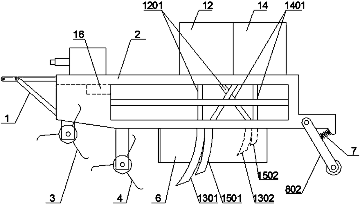
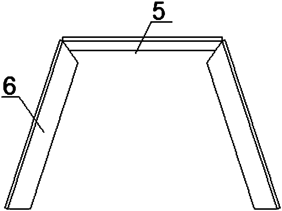
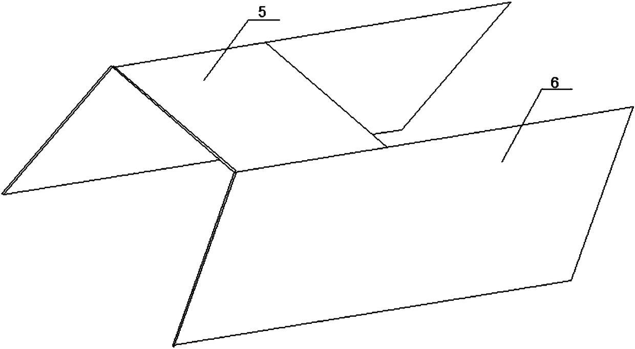
[0020] The present invention relates to a high and low row planting operation machine, comprising a frame 2 connected to the rear end of the tractor by means of a suspension frame 1, and a rotary tillage mechanism, a fertilization mechanism, a seeding mechanism and a suppression mechanism sequentially arranged on the frame 2. The rotary tillage mechanism includes a group of soil-raising rotary tillage wheels and a group of bottom rotary tillage wheels arranged at the bottom of the frame 2 in sequence. Both the soil-lift rotary tiller wheels and the bottom bottom rotary tiller wheels are arranged at intervals, and the soil-lift rotary tillage The operating depth of the wheel is 5-10cm, and the operating depth of the bottom rotary tillage wheel is 5-10cm lower than that of the soil rotary tillage wheel. The fertilizing mechanism and the seeding mechanism on the top; the soil-raising rotary tiller includes a rotating shaft and a soil-raising rotary tiller group 3 on the rotating s...


PUM


Abstract

The invention relates to a high-low-row planting operation machine, which comprises a chassis, a rotary tillage mechanism, a fertilizing mechanism, a seeding mechanism, and a compacting mechanism, thechassis is connected to the rear end of a tractor by means of a hanger, and the rotary tillage mechanism, the fertilizing mechanism, the seeding mechanism and the compacting mechanism are sequentially arranged on the chassis; the rotary tillage mechanism comprises a group of soil-digging rotary tillage wheels and a group of subsoil rotary tillage wheels which are sequentially arranged on the bottom of the chassis; each soil-digging rotary tillage wheel comprises a rotary shaft and soil-digging rotary tillage blades evenly distributed on the surface, and each subsoil rotary tillage wheel comprises a rotary shaft and subsoil rotary tillage blades evenly distributed on the surface. According to the invention, the soil-digging rotary tillage wheels are utilized to carry out rotary tillage onsoil on a straight operation line and turn the subsoil to both sides, so that high ridges are formed, the subsoil rotary tillage wheels are utilized to carry out rotary tillage on subsoil on the straight operation line, and high ridges which are used for crop planting and arranged at intervals are formed by the joint action of both. Compared with the structures of conventional operation machines,the structure does not become complex, high-low-row planting can be realized by planting the same type of crop on the high ridges and furrows, and an increase in the difficulty of operation caused bythe different harvesting methods of different crops is prevented.

Description

technical field [0001] The invention belongs to the technical field of agricultural machinery, and in particular relates to a high-low row planting operation machine. Background technique [0002] After the crops are planted, there are many factors required in the growth period, including water, fertilizer, sunlight, ventilation, etc. The growth height of the same crop after planting is basically the same, which will cause mutual blocking of sunlight and ventilation. Therefore, the existing technology In this method, crops of different heights are planted at intervals, and crop planting rows with high and low intervals are formed. The utilization rate of sunlight between crops of different heights can be maximized, and the ventilation rate has also been significantly improved. However, this method needs to be carried out Multiple planting operations in the field or improvement of the operating machine to realize the planting of multiple crops at one time. In addition, differ...

Claims


Application Information

Patent Timeline
Patent Type & Authority Applications(China)
IPC IPC(8): A01B49/02A01B49/06
CPCA01B49/02A01B49/06
Inventor 高源
Owner 高源
Learn More