
Circuit breaker adapting to user terminal of smart grid, and protection method thereof

A smart grid and circuit breaker technology, applied to circuit devices, emergency protection circuit devices, electrical components, etc., can solve problems such as high price, low sampling accuracy, and single function, so as to prevent excessive temperature, improve sampling accuracy, and shrink effect of size

Pending Publication Date: 2018-09-07
JIANGSU KAILONG ELECTRONICS
View PDF0 Cites 2 Cited by
  • Summary
  • Abstract
  • Description
  • Claims
  • Application Information

AI Technical Summary

Problems solved by technology

[0003] The original circuit breaker can only provide a single protection function. With the development of electronic technology, there are also circuit breakers with communication and data transmission, but their functions are single, the price is high, and communication requires an additional communication module. Especially because the characteristics of the circuit breaker determine that its sampling accuracy is low, which can only meet the requirements for the realization of protection functions, and it is difficult to meet the calculation accuracy requirements of smart grid and big data

Method used


Image

  • Circuit breaker adapting to user terminal of smart grid, and protection method thereof
  • Circuit breaker adapting to user terminal of smart grid, and protection method thereof
  • Circuit breaker adapting to user terminal of smart grid, and protection method thereof

Examples


Embodiment Construction

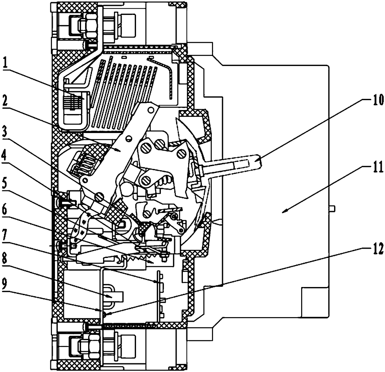
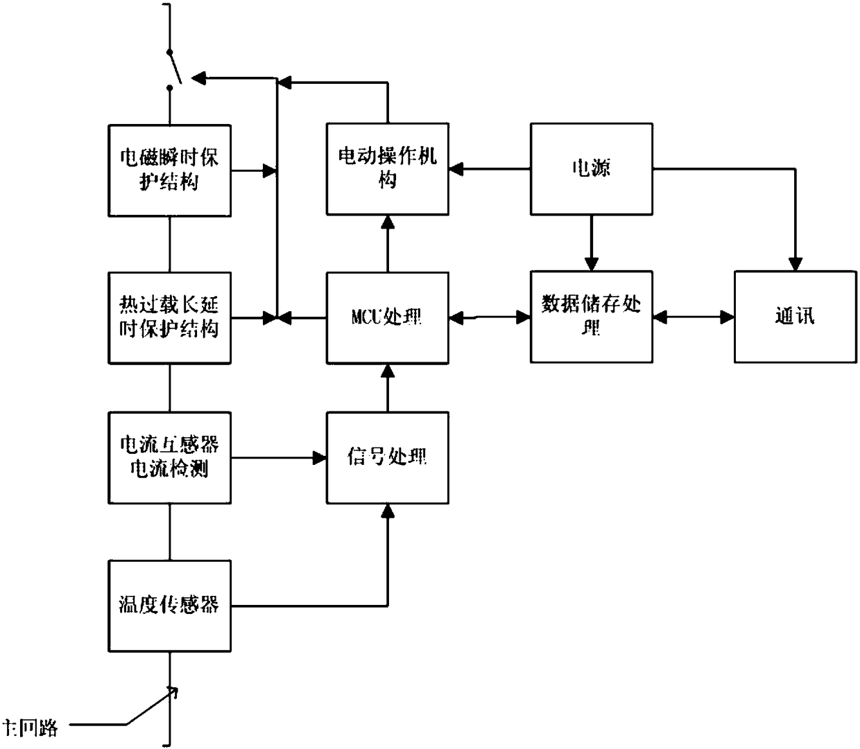
[0041] figure 1 It is a structural representation of the present invention. figure 2 It is a schematic diagram of the principle of the present invention. Such as figure 1 , figure 2 As shown, the circuit breaker includes contacts 2 , tripping mechanism 3 and main circuit busbar 9 . The static contact 1 is fixed inside the circuit breaker, and the tripping mechanism 3 drives the moving contact 3 to rotate. When the tripping mechanism 3 is in the untripped state, the moving contact 2 is in contact with the static contact 1, and when the tripping mechanism 3 is in the tripping state, the moving contact 2 is separated from the static contact 1, and the main The circuit breaks the fault current to realize the protection of the circuit. The main circuit busbar 9 is electrically connected with the moving contact 3.

[0042]Branch wires connected in parallel with the main circuit busbar 9 are installed on the main circuit busbar 9 . A current transformer 8 is installed on th...


PUM


Abstract

The invention discloses a circuit breaker adapting to a user terminal of a smart grid, and a protection method thereof. The circuit breaker comprises contacts, a tripping mechanism and a main lip busbar, wherein the fixed contact is fixed in the circuit breaker, and the tripping mechanism drives a movable contact to rotate; when the tripping mechanism is positioned in a non-tripping state, the movable contact touches the fixed contact, and when the tripping mechanism is positioned in a tripping state, the movable contact is separated from the fixed contact; the main loop busbar is connected with the movable contact; a branch lead parallel to the main loop busbar is installed on the main loop busbar; a current transformer is installed on the branch lead; a thermistor is installed on the main loop busbar; and an electromagnetic instantaneous protection structure, a thermal overload delay protection structure and an electronic protection structure are also installed in the circuit breaker. According to the circuit breaker provided by the invention, besides the protection function, the high precision instrument transformer with full current range measurement is increased, and the highprecision current sample can be applied to protecting the circuit breaker and can also be applied to big data computation.

Description

technical field [0001] The invention relates to a circuit breaker, in particular to a circuit breaker adapted to a smart grid user end and a protection method thereof. Background technique [0002] The circuit breaker is a device used to protect the safety of the power grid and electrical facilities in the power grid. For a long time, the circuit breaker has only played a role in safety protection in the power grid. It is hoped that the circuit breaker can provide more and more reliable real-time data and information. At the same time, with the rapid development and expansion of the power grid, unattended power stations, residential power stations, and rural power stations have higher and higher requirements for power response. It is very important to respond quickly and reduce the outage rate. [0003] The original circuit breaker can only provide a single protection function. With the development of electronic technology, there are also circuit breakers with communication...

Claims


Application Information

Patent Timeline
Patent Type & Authority Applications(China)
IPC IPC(8): H02H7/26H02H7/28H02J13/00
CPCH02J13/0006H02H7/262H02H7/263H02H7/28Y04S10/20Y02E60/00
Inventor 吴晔陈程吴建新
Owner JIANGSU KAILONG ELECTRONICS
Learn More