
Arch tires for lining masonry of industrial furnace pipe tee and construction method of tee masonry

An industrial furnace and inner lining technology, applied in the direction of lining repair, etc., can solve the problems of limited viewing angle, affecting processing quality, low construction efficiency, etc., and achieve the effects of avoiding oppression, improving masonry efficiency, and increasing construction space

Active Publication Date: 2019-08-23
CHINA FIRST METALLURGICAL GROUP
View PDF7 Cites 0 Cited by
  • Summary
  • Abstract
  • Description
  • Claims
  • Application Information

AI Technical Summary

Problems solved by technology

The masonry of the pipeline tee must be connected with long arch tires. The long arch tires are connected by multiple tire pieces and long tire strips. Stake out the processing surface of the refractory bricks, then squat down to process at the bottom of the pipe, and then get up to inspect the processing surface of the bricks. The construction personnel need to get up and squat between the two tires several times every time they build a brick. It will cause a strong sense of oppression, and the construction efficiency is low. During the inspection process of the brick processing surface, the construction personnel are sandwiched between the two tires, and the viewing angle is limited, which affects the processing quality.

Method used


Image

  • Arch tires for lining masonry of industrial furnace pipe tee and construction method of tee masonry
  • Arch tires for lining masonry of industrial furnace pipe tee and construction method of tee masonry
  • Arch tires for lining masonry of industrial furnace pipe tee and construction method of tee masonry

Examples


Embodiment Construction

[0037] In order to have a clearer understanding of the technical features, purposes and effects of the present invention, the specific implementation manners of the present invention will now be described in detail with reference to the accompanying drawings.

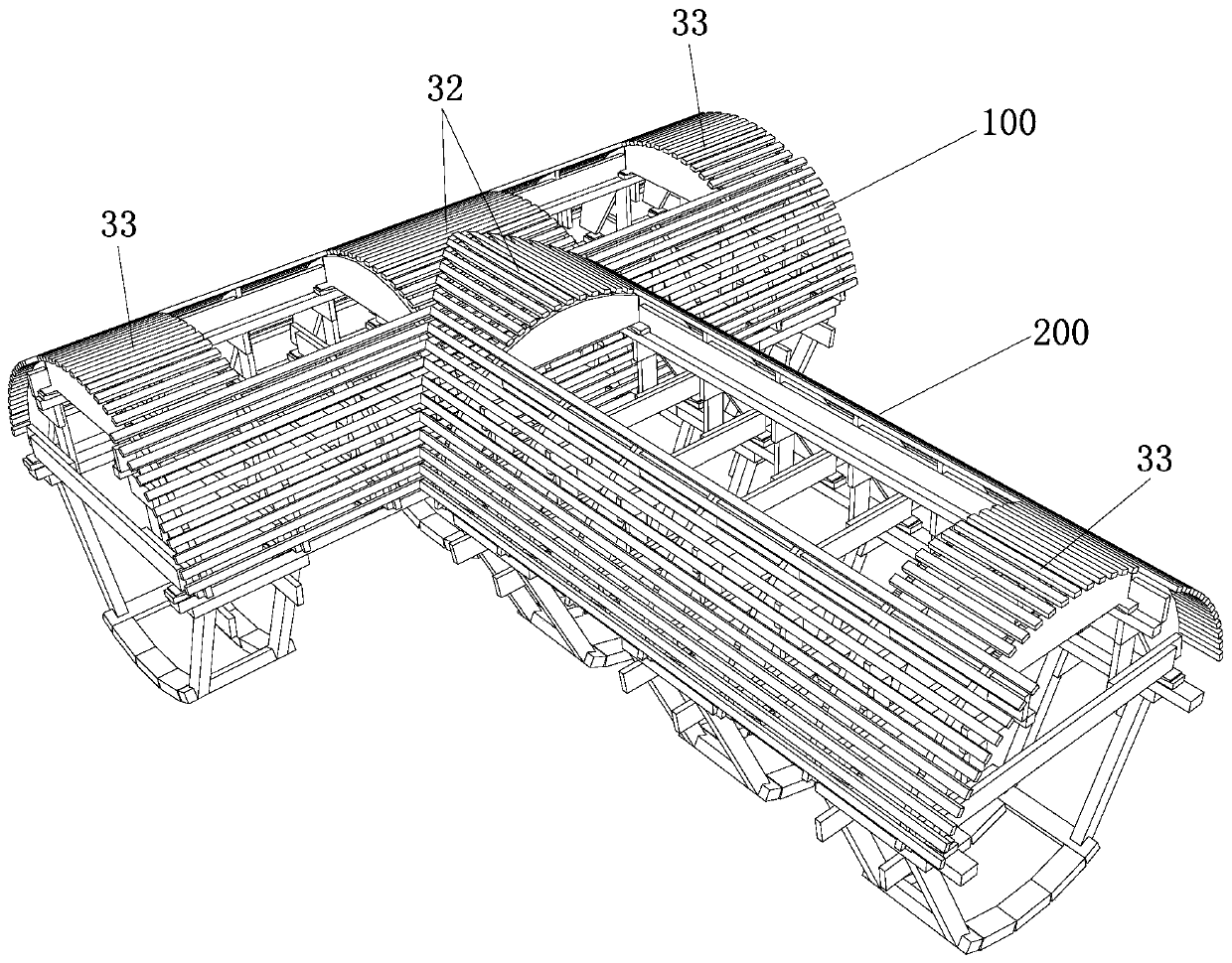
[0038] Such as figure 1Shown is a preferred embodiment of an industrial furnace pipe tee lining masonry tire, including a main pipe tire 100 and a branch pipe tire 200 that are perpendicular to each other and connected to each other.

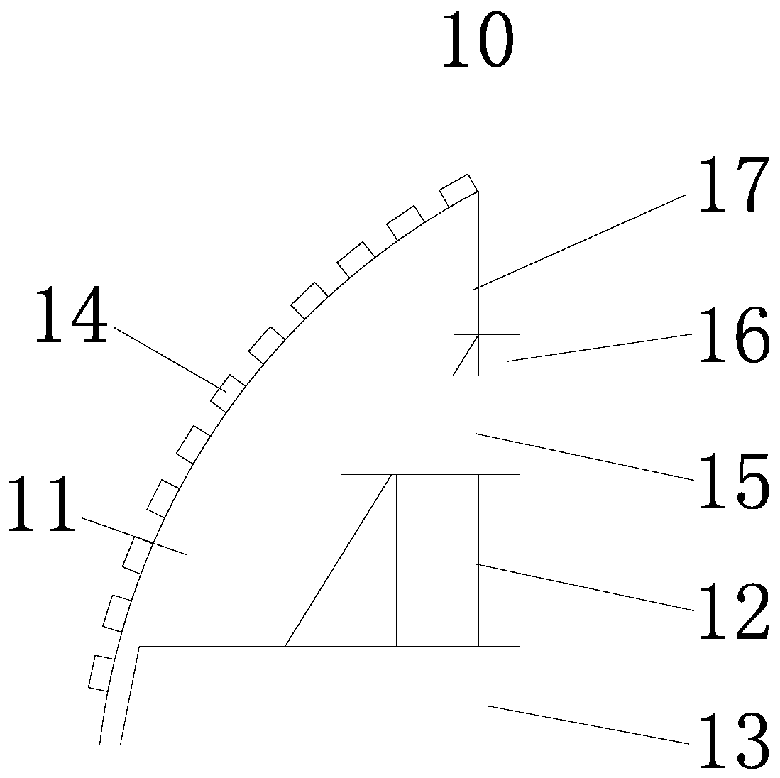
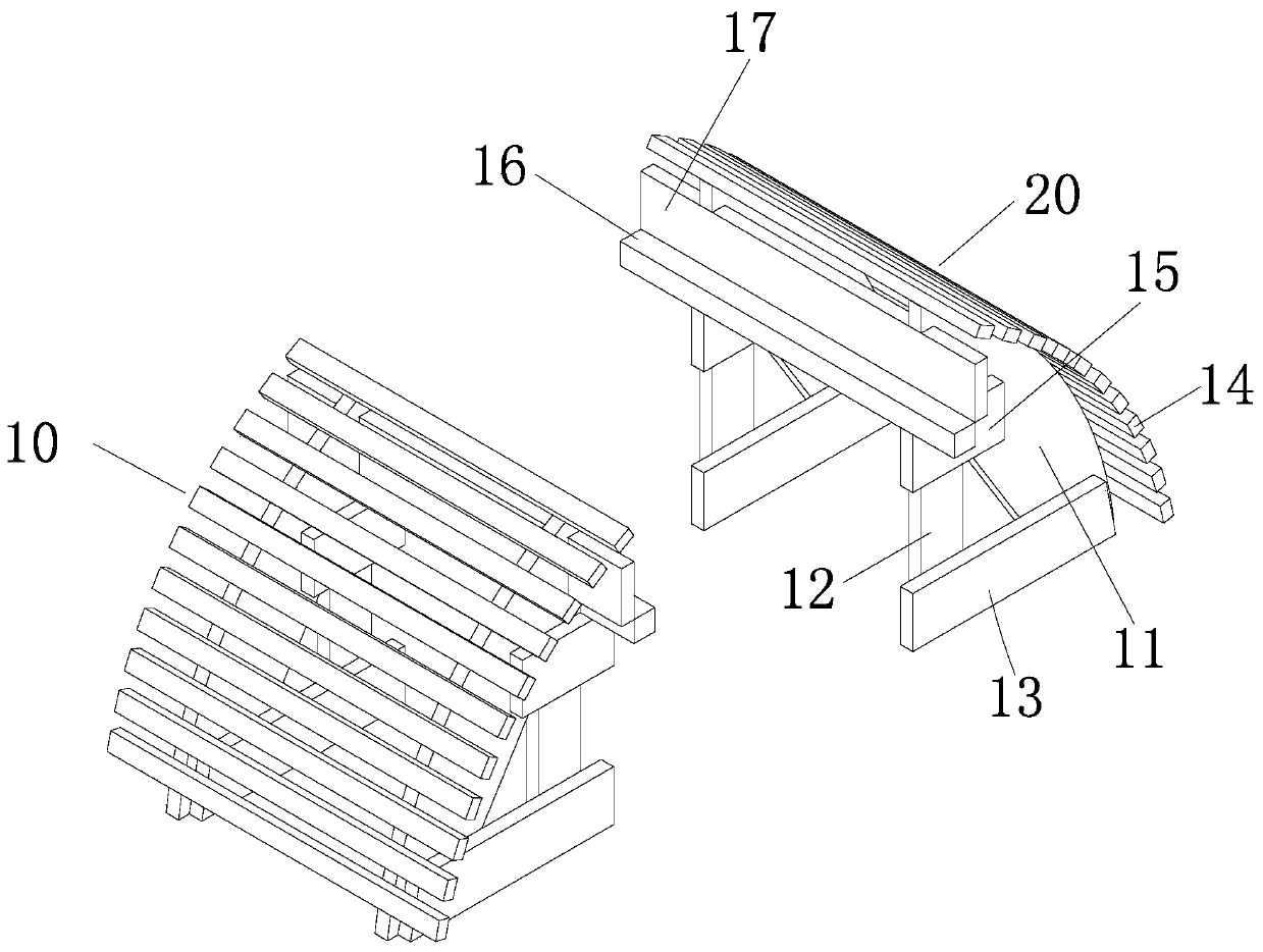
[0039] Such as Figure 2-7 shown, combined with figure 1 , The main pipe tire 100 includes a left valve tire 10 , a right valve tire 20 , a middle tire 30 and a tire support frame 50 . The left valve arch tire 10 comprises a tire strip 14 and some lower arc plates 11, the lower arc plates 11 are flat plates, one side of the flat plate is arc-shaped, the tire strips 14 are fixedly mounted on some lower arc plates 11, and some lower arc plates 11 Arranged evenly along the length directio...


PUM

PropertyMeasurementUnit
lengthaaaaaaaaaa
lengthaaaaaaaaaa

Abstract

The invention relates to an arch mould for lining masonry for a pipeline tee joint of an industrial furnace, and a masonry construction method for a tee joint. The arch mould comprises a left-petal arch mould, a right-petal arch mould, middle arch moulds and an arch mould support frame, wherein the left-petal arch mould and the right-petal arch mould are the same in structure and oppositely arranged; the bottoms of the left-petal arch mould and the right-petal arch mould are fixedly connected through a transversal connection plate; and the middle arch moulds are placed on middle arch mould rails of the left-petal arch mould and the right-petal arch mould, the middle arch moulds move on the middle arch mould rails according to a construction range, the left-petal arch mould, the right-petalarch mould, the middle arch moulds and the arch mould support frame form the arch mould for pipeline lining masonry, and two arch moulds are connected in a penetrating manner to form the arch mould for lining masonry for the pipeline tee joint of the industrial furnace. The method disclosed by the invention is capable of increasing the construction space, thereby avoiding the oppressing sensationof construction personnel in a construction process; setting-out and masonry for the intersecting lines of bricks are facilitated, so that the masonry quality for the tee joint is improved, and the masonry efficiency for the tee joint is increased; and inspection for whether the closed brick joints of the bricks at an arch crown meet requirements or not is facilitated, so that the masonry qualityis improved.

Description

technical field [0001] The invention relates to the technical field of furnace and kiln construction, in particular to an arch tire and a tee masonry construction method for an industrial furnace pipe tee lining masonry. Background technique [0002] The outer surface of the industrial furnace pipe is steel pipe, and the inner lining is made of refractory material for heat insulation. During the lining masonry process, the lining vault is generally supported by arch tires. The arch tires are composed of tire pieces and tire strips. The support range (the length of the tire strips) is the length of the construction worker's arm, about 600 mm. The masonry of the pipe tee must be connected with long arch tires. The long arch tires are connected by multiple tire pieces and long tire strips. Stake out the processing surface of the refractory bricks, then squat down to process at the bottom of the pipe, and then get up to inspect the processing surface of the bricks. The construc...

Claims


Application Information

Patent Timeline
Patent Type & Authority Patents(China)
IPC IPC(8): F27D1/16
Inventor 夏春吴春桥黎耀南吴旭
Owner CHINA FIRST METALLURGICAL GROUP
Learn More