
Evaporator and application thereof in heat pump unit

A technology for evaporators and heat exchange tubes, applied in the field of evaporators assembled by non-welding technology, can solve problems such as medium leakage, achieve the effect of reducing welding quality requirements, reducing welding requirements, and easy replacement

Active Publication Date: 2018-09-07
云南穗特丰农业科技有限公司
View PDF5 Cites 1 Cited by
  • Summary
  • Abstract
  • Description
  • Claims
  • Application Information

AI Technical Summary

Problems solved by technology

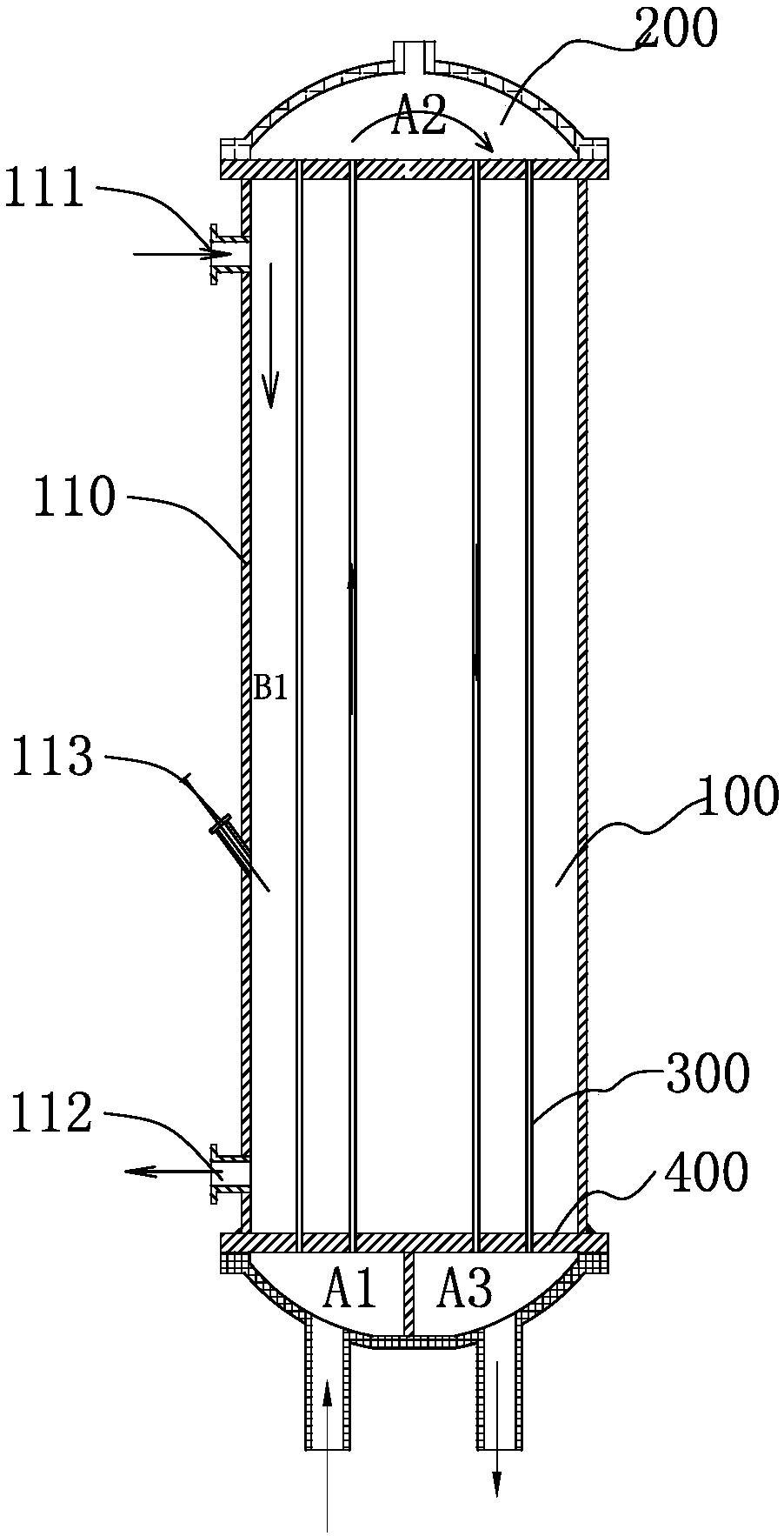
[0011] In order to solve the deficiencies of the prior art, the present invention provides an evaporator of a heat pump unit, which is used to solve the problem that the welding point between the heat exchange tube and the tube sheet in the existing evaporator and heat exchanger is prone to medium leakage

Method used


Image

  • Evaporator and application thereof in heat pump unit
  • Evaporator and application thereof in heat pump unit
  • Evaporator and application thereof in heat pump unit

Examples


Embodiment 2

[0059] refer to Figure 6 , the end of the stainless steel tube 300 is expanded. After the expansion, a large end 310 with a length slightly greater than 2 times the thickness of the tube sheet is formed at both ends of the stainless steel tube. The round hole on the tube sheet 400 corresponds to the expanded hole. Dimensions and other installation steps are basically the same as in Embodiment 1. Before tightening the outer fastening nut, add a step, that is, insert a stainless steel sleeve 600 with tens of degrees below zero into the expansion part, and the specification of the stainless steel sleeve is the same as that of the stainless steel pipe After the sleeve is inserted, tighten the fastening nut. After tightening, the stainless steel sleeve 600 will heat up, and the expansion end of the heat exchange tube can be tightened from the inside. At the same time, the expansion part of the thin wall can be effectively avoided. Local deformation occurs under the locking action ...

Embodiment 3

[0061] refer to Figure 7 , on the basis of Embodiment 1, for the deformation and technical extension of Embodiment 2, a stainless steel sleeve 600 is added, and the end of the stainless steel sleeve has a disc. After the fastening nut is tightened, the stainless steel sleeve is welded Welding, that is, welding connection between the stainless steel sleeve 600 and the fastening nut 530 can increase the loosening capacity of the fastening nut after welding. At the same time, the ends of the heat exchange tubes are limited to prevent axial serial movement.

Embodiment 4

[0063] In the above three embodiments, the above-mentioned stainless steel pipe is a straight pipe, that is to say, a pipe that is straight up and down. In this embodiment, in order to increase the heat exchange effect, the middle part of the heat exchange tube 300 is spirally wound to form a spiral tube 320 in the middle and straight tubes 330 at both ends. Refer to Figure 8 , where the straight pipe part can also form an enlarged end after expanding the hole. During operation, under the thermal expansion and contraction effect of the heat exchange tube, the deformation of the spiral tube itself can avoid the stress of relative sliding between the heat exchange tube and the conical seal, ensuring that the seal is in the best state.


PUM

PropertyMeasurementUnit
thicknessaaaaaaaaaa

Abstract

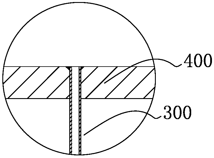
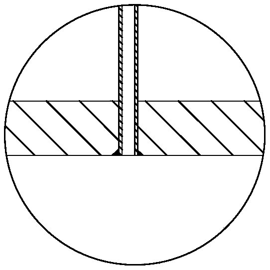
The invention discloses an evaporator and an application thereof. The evaporator is used for solving the problem that a welding part of a heat exchange tube easily leaks. The evaporator comprises a shell pass and a tube pass, wherein a first working medium is introduced into the shell pass, a second medium is introduced into the tube pass, the two ends of the heat exchange tube in the evaporator and a tube plate are in tight fit, the end parts of the two ends of the heat exchange tube extend to the outer side of the tube plate, and the exposed length of the heat exchange tube is not smaller than the thickness of the tube plate; the evaporator comprises an adaptor, a conical sealing part and a locking nut, wherein the adapter comprises a flange part and a cylindrical part, the inner part ofthe cylindrical part is in a cone shape and is filled with a conical sealing part, the flange part and the tube plate are welded and fixed, and the locking nut is fastened on the cylindrical part andcompresses the conical sealing part. According to the evaporator, the adapter is connected with the tube plate in a welding mode, leakage cannot occur; and meanwhile, a first-stage over-tight fit seal and a second-stage seal sleeve seal are arranged between the heat exchange tube, the adapter and the tube plate simultaneously, so that no leakage liquid is generated between the tube pass and the shell pass.

Description

technical field [0001] The invention relates to the technical field of evaporators for heat pumps, especially the evaporator technology assembled by non-welding technology. Background technique [0002] A heat pump is a device that uses high-level energy to flow heat from a low-level heat source to a high-level heat source. Heat pump technology is also an energy-saving technology for low-temperature waste heat utilization. A heat pump unit is usually composed of a compressor, a condenser, an evaporator, a throttling device and an electronic control system. The evaporator plays an important role in the unit. The principle is that the refrigerant is converted from a liquid state to a gas state in the evaporator. After heat absorption, the gaseous refrigerant is sucked into the compressor and compressed into the condenser, where it releases heat and is used for heating, hot water and other normal temperature water. In the condenser, the condensing agent is converted from a hig...

Claims


Application Information

Patent Timeline
Patent Type & Authority Applications(China)
IPC IPC(8): F25B39/02F28F9/14F28F9/18F28F19/04
CPCF25B39/02F28F9/14F28F9/18F28F19/04F28F2230/00F28F2265/16
Inventor 孔瑞清
Owner 云南穗特丰农业科技有限公司
Learn More