Pulseless large-travel plunger pump

A plunger pump and large-stroke technology, which is applied in the field of non-pulsation large-stroke plunger pumps, can solve problems such as increased frictional resistance and wear, decreased pump efficiency, and large pulsation in displacement, so as to improve mechanical efficiency, eliminate contact, and eliminate side force effect

Pending Publication Date: 2018-09-07
MECHANICS RES & DESIGN ACAD SICHUAN PROV
View PDF0 Cites 2 Cited by
  • Summary
  • Abstract
  • Description
  • Claims
  • Application Information

AI Technical Summary

Problems solved by technology

[0002] The plunger pump is the pump with the highest volumetric efficiency, but due to the fact that the stroke depends on the crank connecting rod mechanism, a large stroke is very uneconomical, so the stroke of the plunger pump is limited, so it is very difficult to realize a large displacement plunger pump; and the plunger pump During the movement, the plunger and the cylinder liner bear the periodic lateral pressure transmitted by the crank connecting rod mechanism, so there needs to be good lubrication between the plunger and the cylinder liner wall; due to the inherent characteristics of the crank connecting rod mechanism, the When the input is input, the displacement output of the connecting rod in the direction of the cylinder axis, that is, the displacement, changes in a sine wave, so the output pulsation is large; in order to reduce the internal leakage of the pumped fluid through the gap between the plunger and the cylinder liner, piston rings, piston rings are often used. Contact ring seals in the form of gray rings, which increase frictional resistance and wear;
[0003] Axial-flow pumps have the characteristics of large flow and low pulsation, but are limited by impeller hydrodynamics and material properties, impeller diameter and blade width are limited, single-stage impeller pressure ratio is very limited, and its best performance must be guaranteed The flow rate of the working fluid is near the design point area. When the flow rate deviates, the efficiency drops significantly, and the efficiency is also 0 at 0 flow rate.
[0004] Centrifugal pumps rely on the principle of centrifugal supercharging. The fluid speeds up through the rotating impeller and is thrown to the volute to stop to achieve supercharging. In principle, the single-stage centrifugal impeller with the same speed and diameter is faster than the axial flow impeller. The pressure ratio is much higher, but it is also limited by the mechanical structure and materials; from the analysis of fluid characteristics, the internal flow complexity of the centrifugal pump is more complicated than that of the axial flow impeller, the vortex loss is greater, and the efficiency is lower than that of the axial flow; from the principle Speaking of centrifugal pumps, there is also a problem that the pump efficiency drops significantly at low flow rates, and the efficiency is 0 at 0 flow rates.
[0005] As a positive displacement pump, the rotor pump also has the characteristics of high volumetric efficiency of the positive displacement pump. From the structural point of view, the structure of the rotor and pump casing of the rotor pump is complicated, and the processing is difficult. At the same time, the tooth end seal of the rotor pump is a linear seal, which requires The sealing plate is in contact with the pump casing and has a certain contact pressure, but the result still cannot solve the problem of seal wear and heat dissipation; constrained by the principle of the rotor pump, it is also very difficult to achieve a large displacement structurally
At the same time, there is no linear relationship between the displacement of the rotor pump and the rotation angle of the rotor, so when the rotor moves at a constant speed, the displacement also has a large pulsation

Method used


Image

  • Pulseless large-travel plunger pump
  • Pulseless large-travel plunger pump
  • Pulseless large-travel plunger pump

Examples


Embodiment Construction

[0027] The present invention will be further described below in conjunction with accompanying drawing and specific embodiment:

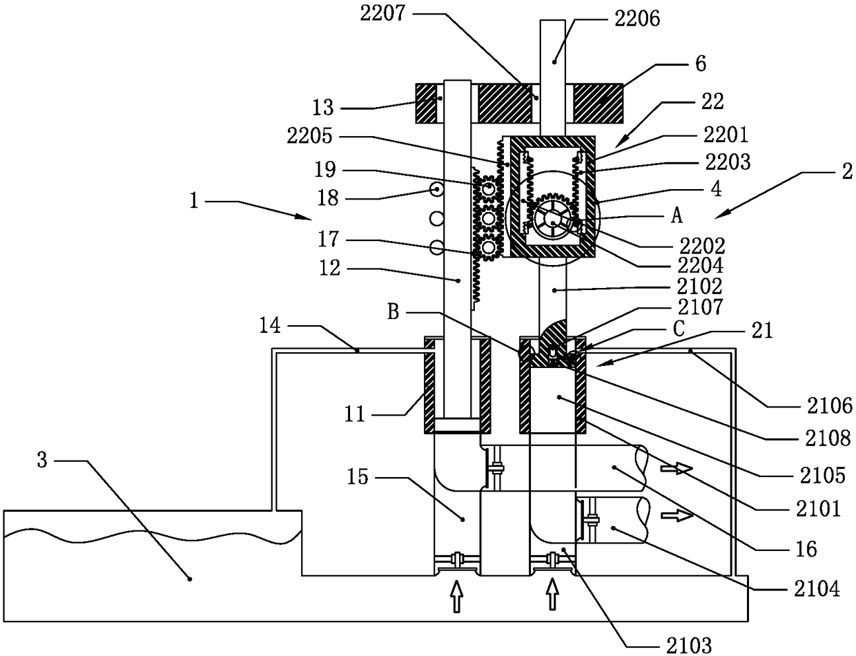
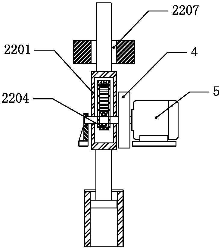
[0028] Such as Figure 1 to Figure 5 As shown, a non-pulsation large-stroke plunger pump provided by the present invention includes a first plunger part 1, a second plunger part 2, a fluid storage device 3 and a connecting part 6, the first plunger part 1 and the second plunger part The lower ends of the plunger parts 2 communicate with the fluid storage device 3 respectively, the first plunger part 1 and the second plunger part 2 are connected through the connecting part 6, the second plunger part 2 is connected with the driving motor 5 through the flywheel 4, and the driving motor 5 When working, it drives the second plunger part 2 to move up and down, and the second plunger part 2 drives the first plunger part 1 to move up and down.

[0029] The second plunger part 2 includes a second plunger pump device 21 and a gear transmission device 22, the ...


PUM


Abstract

The invention discloses a pulseless large-travel plunger pump which comprises a first plunger piece, a second plunger piece, a fluid storage device and a connection piece; the lower ends of the firstplunger piece and the second plunger piece are communicated with the fluid storage device; the first plunger piece and the second plunger piece are connected with each other through the connection piece; the second plunger piece is connected with a drive motor through a flywheel; and the drive motor drives the second plunger piece to move up and down when working, and the second plunger piece drives the first plunger piece to move up and down. The pulseless large-travel plunger pump provided by the invention cancels a contact type sealing structure, realizes non-contact sealing of plungers anda cylinder wall and linear movement of the plungers, solves the problems of displacement pulse and pressure pulse, basically eliminates a lateral force of the plungers to a cylinder sleeve, solves the problems of lubrication, heat dissipation and contact and sliding abrasion between each plunger and the cylinder sleeve and can realize a large-displacement plunger pump design.

Description

technical field [0001] The invention belongs to the technical field of plunger pumps, and in particular relates to a non-pulsation large-stroke plunger pump. Background technique [0002] The plunger pump is the pump with the highest volumetric efficiency, but due to the fact that the stroke depends on the crank connecting rod mechanism, a large stroke is very uneconomical, so the stroke of the plunger pump is limited, so it is very difficult to realize a large displacement plunger pump; and the plunger pump During the movement, the plunger and the cylinder liner bear the periodic lateral pressure transmitted by the crank connecting rod mechanism, so there needs to be good lubrication between the plunger and the cylinder liner wall; due to the inherent characteristics of the crank connecting rod mechanism, the When the input is input, the displacement output of the connecting rod in the direction of the cylinder axis, that is, the displacement, changes in a sine wave, so the...

Claims


Application Information

Patent Timeline
Patent Type & Authority Applications(China)
IPC IPC(8): F04B23/06F04B17/03F04B53/00
CPCF04B17/03F04B23/06F04B53/00
Inventor 李志伟刘恒龙
Owner MECHANICS RES & DESIGN ACAD SICHUAN PROV
Why Eureka
Try Eureka