
Side-prevention type assemble clamping position device for ship part

A clamping device and parts technology, applied in workpiece clamping devices, manufacturing tools, etc., can solve problems such as damage, errors, and affecting ship operation accuracy, and achieve the effects of improving efficiency, ensuring stability, and reducing safety accidents

Inactive Publication Date: 2018-09-07
当涂县金龙凤科技股份有限公司
View PDF7 Cites 0 Cited by
  • Summary
  • Abstract
  • Description
  • Claims
  • Application Information

AI Technical Summary

Problems solved by technology

[0005] Aiming at the deficiencies of the prior art, the present invention provides an anti-side assembly clamping device for ship parts, which is equipped with anti-side and anti-deviation, and prevents errors when equipping ship parts, which affects processing efficiency and In the case of high precision, reducing the error during assembly can not only improve the assembly efficiency of the ship, but also prevent the error from causing potential safety hazards during the operation of the ship, and improve the safety performance during navigation. During the assembly process, it will be affected by the ship parts, which will lead to deviation and side position, which will not only affect the assembly efficiency of ship parts, but also cannot guarantee the assembly accuracy of ship parts, and it is easy to appear tiny after the equipment is completed. When the whole assembly is assembled together, the error will affect the overall running accuracy of the ship. When used for a long time, it will not only affect the smooth operation of the parts, but also easily cause damage between the parts.

Method used


Image

  • Side-prevention type assemble clamping position device for ship part
  • Side-prevention type assemble clamping position device for ship part
  • Side-prevention type assemble clamping position device for ship part

Examples


Embodiment Construction

[0032] The following will clearly and completely describe the technical solutions in the embodiments of the present invention with reference to the accompanying drawings in the embodiments of the present invention. Obviously, the described embodiments are only some, not all, embodiments of the present invention. Based on the embodiments of the present invention, all other embodiments obtained by persons of ordinary skill in the art without making creative efforts belong to the protection scope of the present invention.

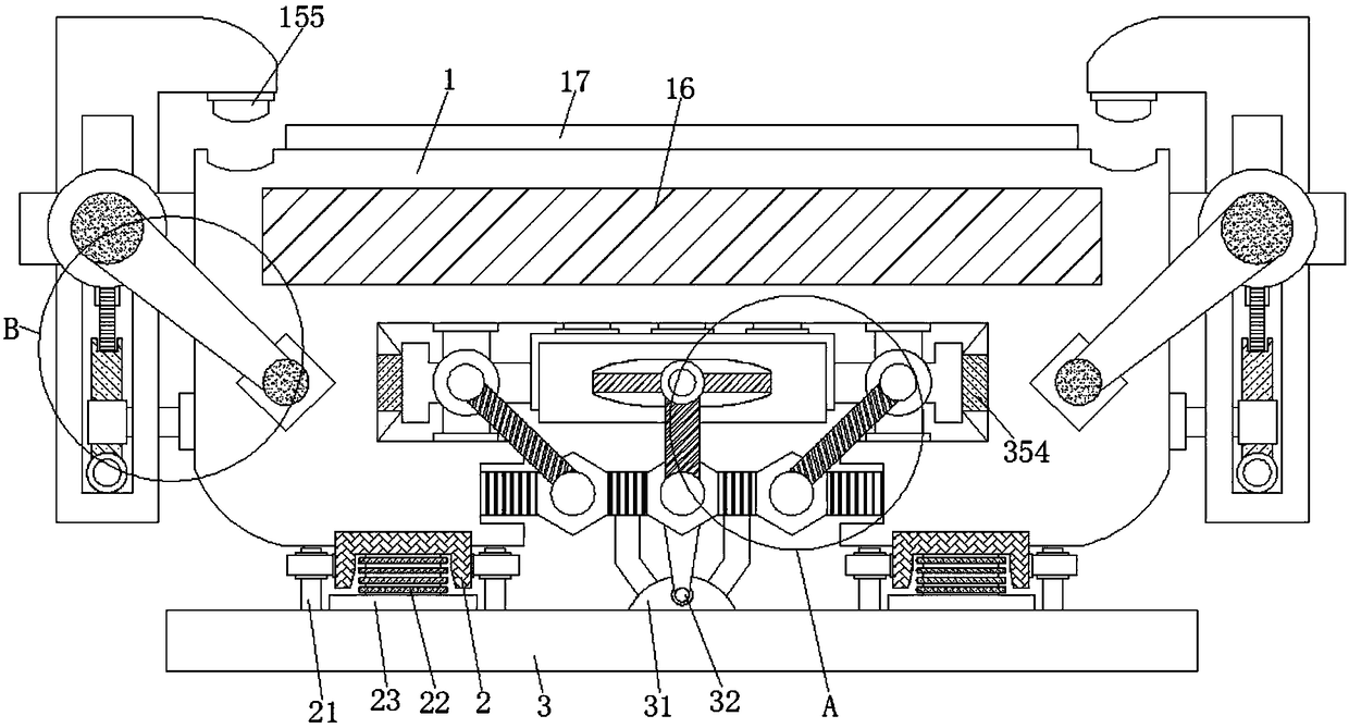
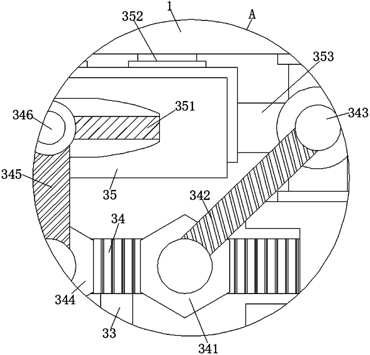
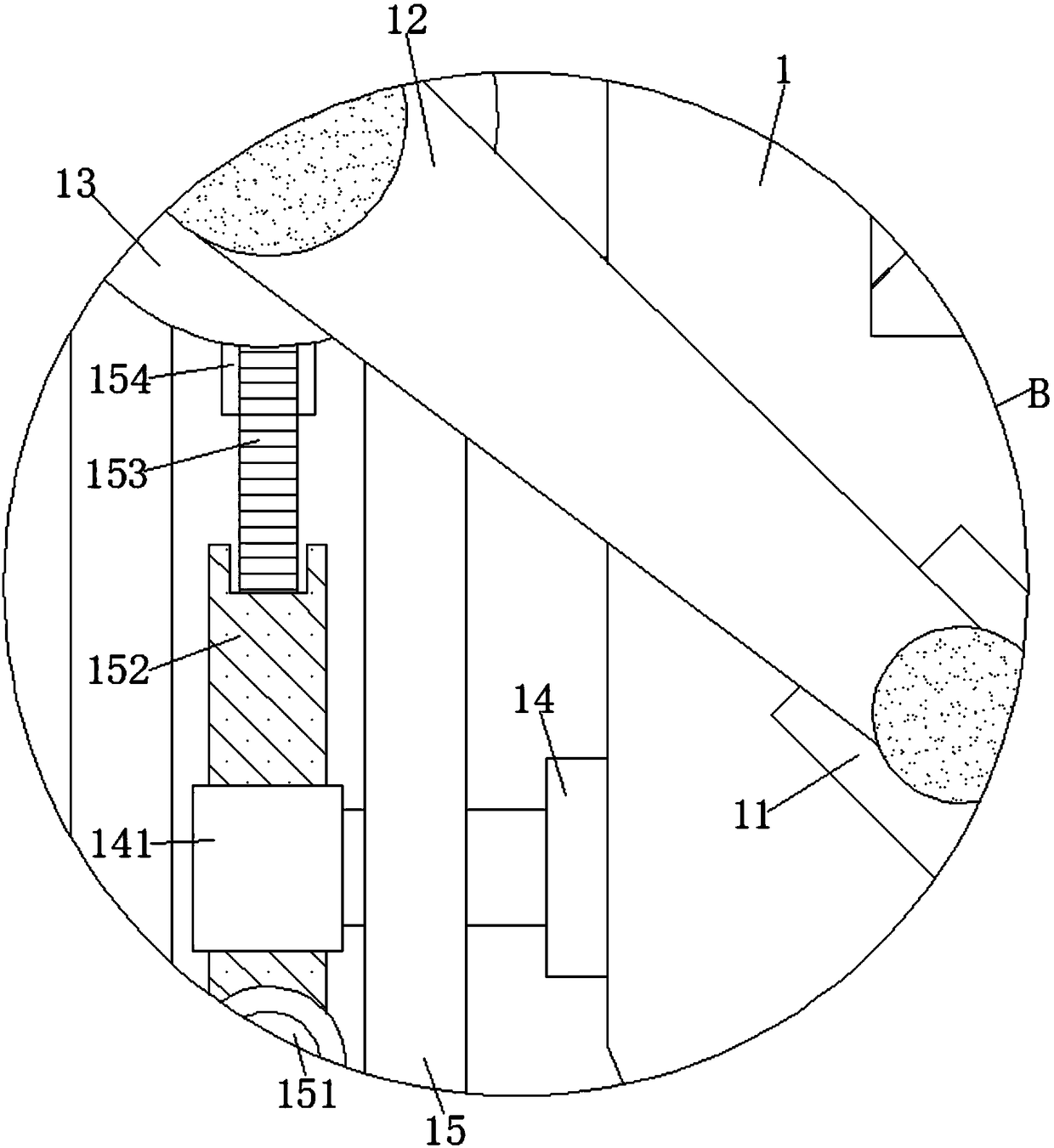
[0033] see Figure 1-5 , an anti-side assembly clamping device for ship parts, including an operation platform 1, the middle of the operation platform 1 on both sides is connected with a latitude adjustment device 11, and the outer surfaces of the two latitude adjustment devices 11 are fitted There are adjustment stay cords 12, and the other ends of the two adjustment stay cords 12 are sleeved on the outer surface of the adjustment slide seat 13. The bottom of...


PUM


Abstract

The invention relates to the technical field of ship correlation, and discloses a side-prevention type assemble clamping position device for a ship part. The device comprises an operation table, bearing supporting devices are welded to the two sides of the bottom of the operation table correspondingly, anti-inclination devices are welded to the two sides of the bearing supporting devices correspondingly, and the bottoms of the two anti-inclination devices are welded with the outer surface of the top of a base correspondingly; an arc-shaped operating device is welded to the middle of the top ofthe base, positioning supporting devices are welded to the bottoms of the two sides of the outer surface of the operating table correspondingly, and one ends of the two positioning supporting devicespenetrate through two driving mechanisms correspondingly and are sleeved with limiting sleeve plates; and a mold table is welded to the middle of the top of the operation table. According to the device, the ship part needing to be assembled is placed on a carrying object seat in the mold table, a latitude adjusting device, the arc-shaped operating device and a position adjusting device are operated to carried out anti-side-position machining, so that the ship part is prevented from being influenced by the acting force during a assembling process to influence the follow-up assembling precisionand efficiency.

Description

technical field [0001] The invention relates to the technical field related to ships, in particular to a side-proof assembly and locking device for ship parts. Background technique [0002] A ship is a man-made means of transportation that primarily operates in geographical waters. In addition, civilian ships are generally called ships, military ships are called ships, and small ships are called boats or boats, which are collectively called ships or boats. The interior mainly includes accommodation space, support structure and drainage structure, and has a propulsion system that utilizes external or self-contained energy. The appearance is generally a streamlined envelope that is conducive to overcoming fluid resistance. The materials are constantly updated with the advancement of science and technology. In the early days, they were natural materials such as wood, bamboo, and hemp. In modern times, they are mostly steel, aluminum, glass fiber, acrylic, and various composite...

Claims


Application Information

Patent Timeline
IPC IPC(8): B25B11/02
CPCB25B11/02
Inventor 张万宝
Owner 当涂县金龙凤科技股份有限公司
Learn More