Dust recycling device for industrial waste gas treatment
A technology of industrial waste gas and dust collection device, which is applied in the direction of combination device, transportation and packaging, separation method, etc. It can solve the problems of easy blockage of filter screen and failure to collect, etc., and achieve the effect of easy recycling and close cooperation
- Summary
- Abstract
- Description
- Claims
- Application Information
AI Technical Summary
Problems solved by technology
Method used
Image
Examples
specific Embodiment approach 1
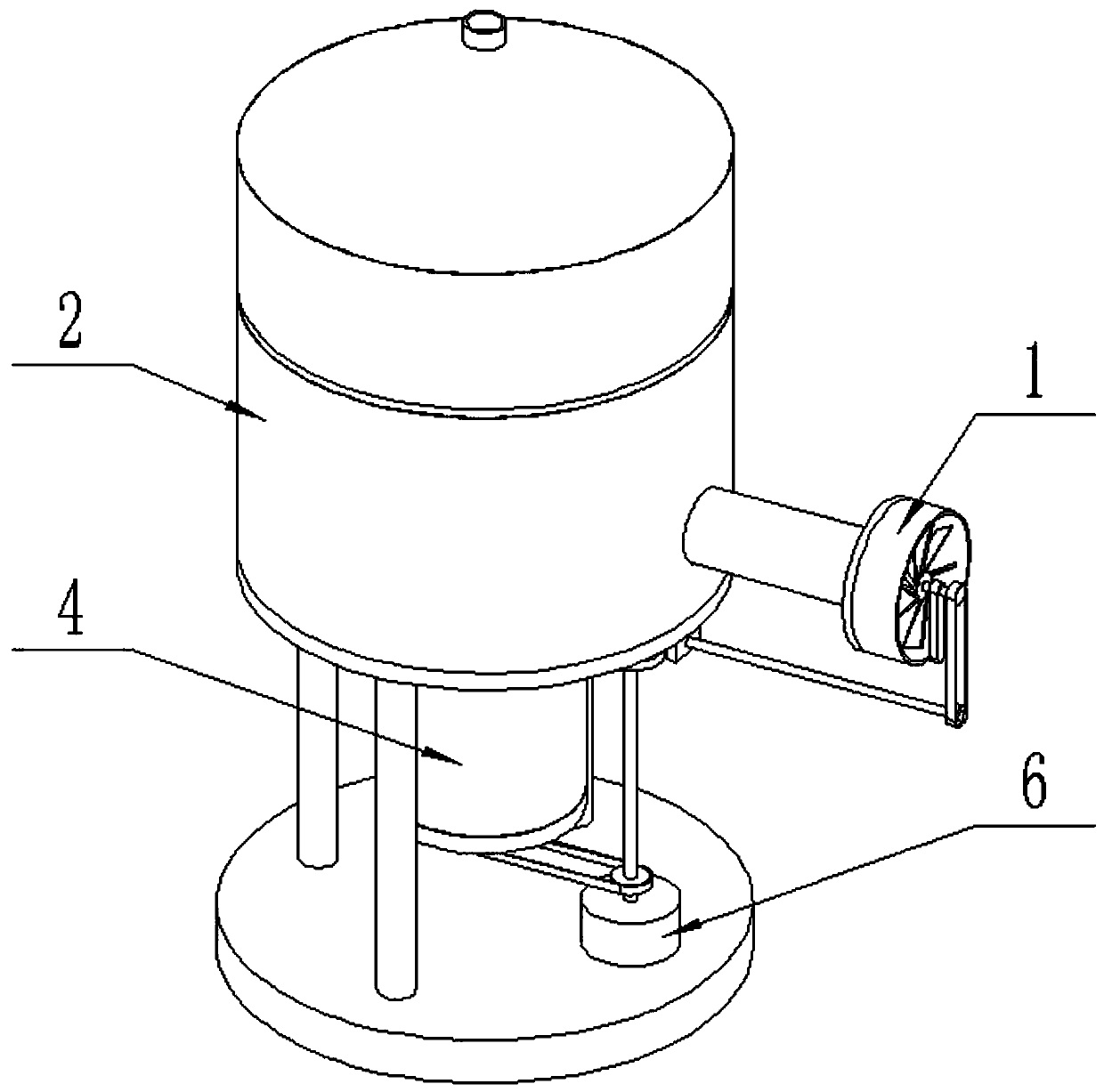
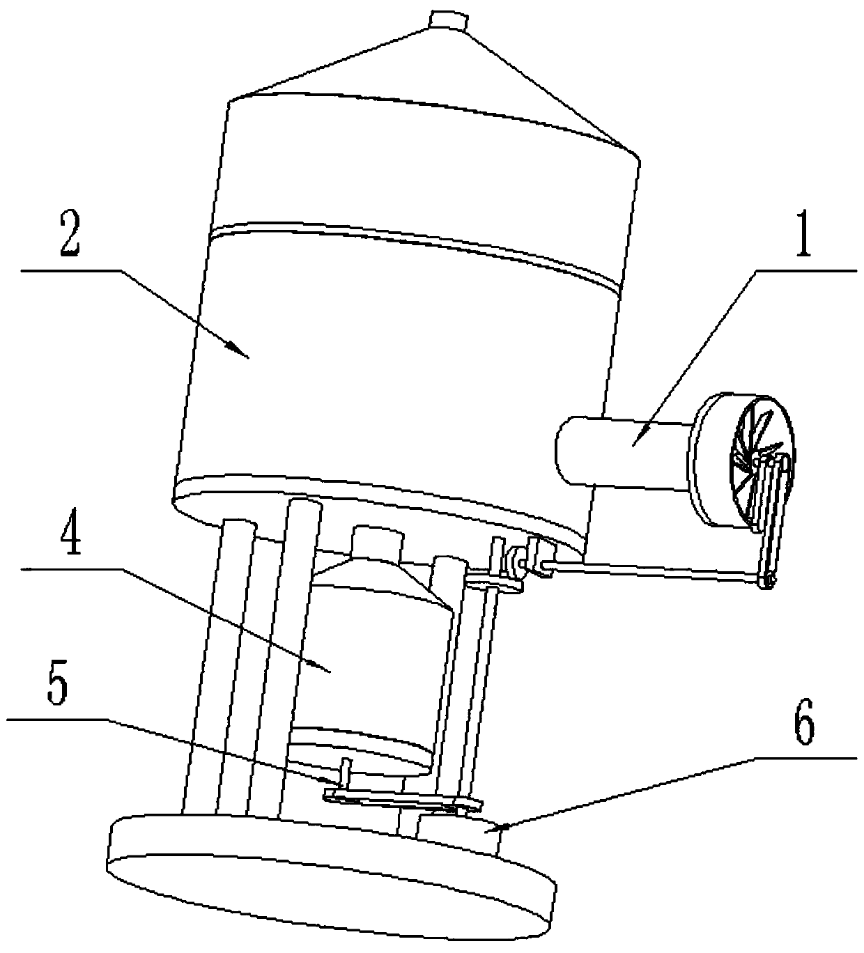
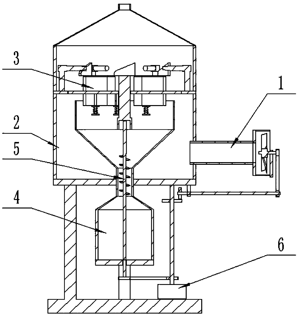
[0032] Such as Figure 1-14As shown, the dust recycling device for industrial waste gas treatment includes a suction pipe assembly 1, a dust removal cylinder assembly 2, a rotating dust filter device 3, a dust collection box assembly 4, an auxiliary dust collection device 5 and a drive control device 6, The dust removal cylinder assembly 2 includes an upper cylinder body 2-1, a lower cylinder body 2-2, an annular mounting plate 2-3, a blocking dust drop rod 2-4, a support base 2-5 and an air outlet pipe 2-6; The upper end of the annular mounting plate 2-3 is fixedly connected to the upper cylinder 2-1, the lower end of the annular mounting plate 2-3 is fixedly connected to the lower cylinder 2-2, and the bottom end of the lower cylinder 2-2 is connected to the On the support base 2-5; the top of the upper cylinder 2-1 is welded and connected to the air outlet pipe 2-6; the top surface of the annular mounting plate 2-3 is evenly surrounded by six blocking and falling dust rods ...
specific Embodiment approach 2
[0034] Such as Figure 1-14 As shown, the suction pipe assembly 1 includes a suction pipe body 1-1, a suction fan 1-2, a fan shaft 1-3, a rotating wheel 1-4 and a pedestal plate 1-5; the suction pipe The left end of the main body 1-1 is connected to and communicated with the lower cylinder 2-2; the right end of the suction pipe main body 1-1 is fixedly connected to the shaft frame plate 1-5; the fan shaft 1-3 passes through the bearing housing with bearings Connected to the pedestal plate 1-5, the left end of the fan shaft 1-3 is fixedly connected to the suction fan 1-2, and the suction fan 1-2 is rotated and connected to the right end of the suction pipe body 1-1; The right end of the fan shaft 1-3 is fixedly connected to the rotating wheel 1-4; the rotating wheel 1-4 is connected to the drive control device 6 through a belt. When the suction pipe assembly 1 is in use, the rotating wheel 1-4 rotates under the drive of the drive control device 6, the rotating wheel 1-4 drives...
specific Embodiment approach 3
[0036] Such as Figure 1-14 As shown, the drive control device 6 includes a drive motor 6-1, a drive shaft 6-2, a driven shaft 6-3, a drive sprocket 6-4, a drive bevel gear 6-5, a drive bevel gear 6-6, a vertical The seat plate 6-7 and the linkage wheel 6-8; the drive motor 6-1 is fixedly connected to the support base 2-5, and the output end of the drive motor 6-1 is connected to the transmission shaft 6-2 through a coupling; The lower end of the transmission shaft 6-2 is fixedly connected to the transmission sprocket 6-4, and the transmission sprocket 6-4 is connected to the auxiliary dust collecting device 5 through a chain; the upper end of the transmission shaft 6-2 is fixedly connected to the transmission bevel gear 6-5, and the transmission The bevel gear 6-5 meshes with the passive bevel gear 6-6; the passive bevel gear 6-6 is fixedly connected to the left end of the driven shaft 6-3, and the driven shaft 6-3 is connected to the vertical seat plate through a bearing sea...
PUM
 Abstract
Description
Claims
Application Information
 - R&D
- Intellectual Property
- Life Sciences
- Materials
- Tech Scout
- Unparalleled Data Quality
- Higher Quality Content
- 60% Fewer Hallucinations
Browse by: Latest US Patents, China's latest patents, Technical Efficacy Thesaurus, Application Domain, Technology Topic, Popular Technical Reports.
© 2025 PatSnap. All rights reserved.Legal|Privacy policy|Modern Slavery Act Transparency Statement|Sitemap|About US| Contact US: help@patsnap.com


