Water-free cooling energy-saving and environmentally-friendly high-power rectification system
A technology of energy saving, environmental protection, rectification system, applied in transformer/inductor cooling, cooling/ventilation/heating renovation, electrical components, etc. Water cooling, small footprint, and increased aesthetics
- Summary
- Abstract
- Description
- Claims
- Application Information
AI Technical Summary
Problems solved by technology
Method used
Image
Examples
Embodiment 1
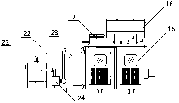
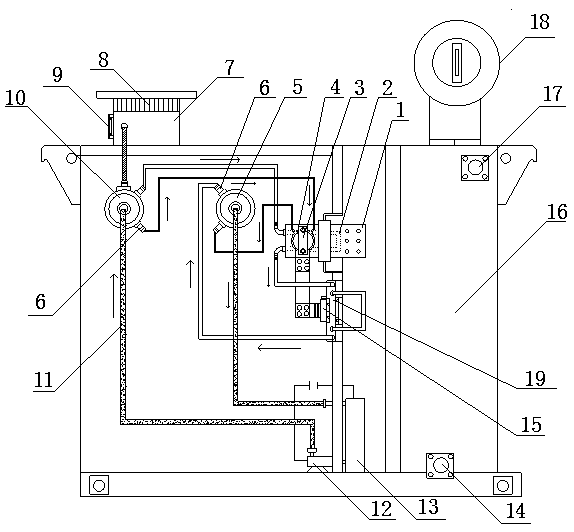
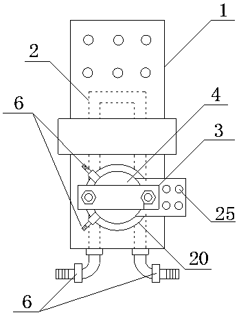
[0036] Such as figure 1 , 2 , 3, a waterless cooling energy saving and environmental protection high-power rectification system, including transformer strong oil circulation cooling main system and rectification internal circulation cooling subsystem;
[0037]The transformer strong oil circulation cooling main system includes a transformer body 16, a strong oil circulation cooler 21, a strong oil cooling circulation pump 24, a strong oil inlet pipe 22 and a strong oil outlet pipe 23; The oil inlet 14 of the strong oil circulation cooler matched with the liquid pipe 22 and the oil outlet 17 of the strong oil circulation cooler matched with the strong oil outlet pipe 23; one end of the strong oil inlet pipe 22 is connected with the strong oil circulation cooler 21 , the other end is connected with the oil inlet 14 of the strong oil circulation cooler, one end of the strong oil outlet pipe 23 is connected with the strong oil cooling circulation pump 24, and the other end is conn...
Embodiment 2
[0045] Such as figure 1 , 2 , 3, a waterless cooling energy saving and environmental protection high-power rectification system, including transformer strong oil circulation cooling main system and rectification internal circulation cooling subsystem;
[0046] The transformer strong oil circulation cooling main system includes a transformer body 16, a strong oil circulation cooler 21, a strong oil cooling circulation pump 24, a strong oil inlet pipe 22 and a strong oil outlet pipe 23; The oil inlet 14 of the strong oil circulation cooler matched with the liquid pipe 22 and the oil outlet 17 of the strong oil circulation cooler matched with the strong oil outlet pipe 23; one end of the strong oil inlet pipe 22 is connected with the strong oil circulation cooler 21 , the other end is connected with the oil inlet 14 of the strong oil circulation cooler, one end of the strong oil outlet pipe 23 is connected with the strong oil cooling circulation pump 24, and the other end is con...
Embodiment 3
[0057] Such as Figure 4 , 5 As shown, the difference between this embodiment and embodiment 2 is:
[0058] There is a relatively large liquid pipe joint on the liquid inlet pipe as the main joint of the general liquid inlet pipe. Arranged on the pipe wall of the liquid inlet pipe, as a branch joint of the liquid pipe, it is correspondingly connected to the liquid pipe joint of the liquid outlet pipe. Similarly, a relatively large main liquid pipe joint is provided on the liquid outlet pipe And the branch joint of the liquid pipe arranged on the pipe wall of the liquid outlet main pipe collects the liquid pipe branch joint on the liquid inlet main pipe, and then sends the cooling liquid with heat into the cooling radiator for circulation and cooling.
[0059] The working principle of this embodiment is the same as that of Embodiment 1.
PUM
 Abstract
Description
Claims
Application Information
 - R&D
- Intellectual Property
- Life Sciences
- Materials
- Tech Scout
- Unparalleled Data Quality
- Higher Quality Content
- 60% Fewer Hallucinations
Browse by: Latest US Patents, China's latest patents, Technical Efficacy Thesaurus, Application Domain, Technology Topic, Popular Technical Reports.
© 2025 PatSnap. All rights reserved.Legal|Privacy policy|Modern Slavery Act Transparency Statement|Sitemap|About US| Contact US: help@patsnap.com


