
Pick-and-place mechanism for circular combing link of silk spinning production line

A production line and circular comb technology, applied in textiles and papermaking, deburring devices, fiber processing, etc., can solve the problems of high work intensity, low safety, and manual processing.

Active Publication Date: 2018-09-04
JINLING INST OF TECH
View PDF20 Cites 2 Cited by
  • Summary
  • Abstract
  • Description
  • Claims
  • Application Information

AI Technical Summary

Problems solved by technology

However, the automation of traditional silk spinning circular comb equipment is low. In the traditional circular comb production, it is necessary to manually put the sliver into the circular comb machine for carding, and take out the combed cotton and put it into the circular comb again after changing the direction, so that the sliver The other end of the
In addition, manual processing is also required in the removal of cotton
In short, the traditional silk spinning circular combing equipment needs a lot of manpower, high manual requirements, high work intensity of workers, and low safety.
[0005] At the same time, in the traditional circular comb production, it is necessary to manually put the sliver into the circular comb machine for combing, and manually take out the combed end of the cotton and reverse it and put it into the circular comb again so that the other end of the cotton can also be finely combed. Take out the doff from the combing cylinder, that is, the traditional silk spinning circular combing equipment has many manual operations, high manual labor intensity, and low labor safety for workers.

Method used


Image

  • Pick-and-place mechanism for circular combing link of silk spinning production line
  • Pick-and-place mechanism for circular combing link of silk spinning production line
  • Pick-and-place mechanism for circular combing link of silk spinning production line

Examples


Embodiment Construction

[0019] Below in conjunction with accompanying drawing and specific embodiment the present invention is described in further detail:

[0020] The invention provides a pick-and-place mechanism for a circular comb link in a silk spinning production line. The invention is mainly aimed at redesigning and optimizing the sub-splint. Based on the existing circular comb machine, it is designed to be automatically taken out from the cylinder skeleton of the circular comb machine. Put it into the device of the auxiliary splint and connect it with the front and rear conveyor belts.

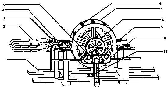
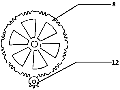
[0021] As an embodiment of the structure of the present invention, the present invention provides a pick-and-place mechanism for a circular comb link in a silk spinning production line, including a frame 1, a turning mechanism 3, an incomplete gear 5, a circular comb cylinder 7, and an irregular gear 8. Limiting guide rail 9, rack push rod 10, motor 11, incomplete gear 2 12, rack 13, guide rail frame 14 and L...


PUM


Abstract

The invention relates to a pick-and-place mechanism for a circular combing link of a silk spinning production line. Circular comb cylinders are mounted on a machine frame, limiting guide rails are arranged at the front and rear ends of the circular comb cylinders, a pair of limiting guide rails are located between the circular comb cylinders and a turning mechanism, embedded cotton plates for turning over are fixed between two cam grooved frames, four-blade grabbing plates are arranged between the embedded cotton plates for turning over and the cam grooved frames, embedded cotton plates for circular combing are arranged on the inner walls of the two circular comb cylinders, irregular gears are arranged at both ends of the circular comb cylinders, second incomplete gears are arranged belowthe irregular gears, first incomplete gears are arranged at the outer sides of the second incomplete gears, racks are arranged on the upper and lower portions of the first incomplete gears, the racksare fixed on rack push rods, the rack push rods at the upper and lower ends are connected through an arc connecting bracket, the arc connecting bracket is connected with movable guide rail ends of guide rail frames, and movable guide rails of each of the movable guide rail frames are connected with a pair of L-shaped push rods. According to the pick-and-place mechanism, a device for automaticallytaking out and placing auxiliary clamping plates from circular comb cylinder skeletons is designed and is connected with front and rear conveyor belts.

Description

technical field [0001] The invention relates to the field of circular comb devices for silk spinning, in particular to a pick-and-place mechanism for circular comb links in a silk spinning production line. Background technique [0002] With the continuous development of silk spinning technology, traditional silk spinning machines have been continuously improved, and traditional silk spinning technology has been continuously improved. Scholars around the world have conducted a lot of explorations on traditional silk spinning machines and achieved fruitful results. However, most of them only focus on improving the efficiency and precision of carding, and have not made a major breakthrough in automated silk spinning. [0003] The traditional silk spinning industry mainly forms a production line based on mechanical production and supplemented by manual operation. In terms of semi-automatic production of silk spinning machinery, my country's technical level has been greatly impr...

Claims


Application Information

Patent Timeline
Patent Type & Authority Applications(China)
IPC IPC(8): D01G15/04D01G15/36D01G15/14
CPCD01G15/04D01G15/14D01G15/36
Inventor 徐华成倪钘凯卢加健张远朱利强万宏缪秋华毛志伟
Owner JINLING INST OF TECH
Learn More