
waste tire shredder

A shredder and waste tire technology, which is applied in the direction of mechanical material recycling, plastic recycling, recycling technology, etc., can solve problems such as low efficiency, damaged cutter head, difficult operation, etc., to save heating time and speed up softening speed , The effect of accelerating the softening speed

Active Publication Date: 2019-10-29
常州绿境环保科技有限公司
View PDF7 Cites 2 Cited by
  • Summary
  • Abstract
  • Description
  • Claims
  • Application Information

AI Technical Summary

Problems solved by technology

[0002] my country is the third largest tire producer in the world, so a large number of waste tire processing equipment has appeared on the market. The waste tire primary shredder currently in use is to put the whole waste tire on the whole tire conveyor and send it to the whole tire shredder for processing. Crushing, through the repeated crushing of the cutter head, and finally the rubber block is discharged from the screen. The raw material of the rubber block is rubber material with high elasticity. The ordinary cutter head is easily broken and the cutter head is damaged, and the efficiency is not high. The rubber blocks are easy to get stuck on the mesh of the screen, and the subsequent rubber blocks will pile up on the original rubber blocks to cause blockage. Once the blockage is too much, it will cause the machine to jam, which is extremely difficult to operate. At this time, it needs to be cleaned manually. Mesh, not only dangerous but extremely inefficient

Method used


Image

  • waste tire shredder
  • waste tire shredder
  • waste tire shredder

Examples


Embodiment Construction

[0018] In order to enable those skilled in the art to better understand the solutions of the present invention, the technical solutions in the embodiments of the present invention will be clearly and completely described below in conjunction with the drawings in the embodiments of the present invention. Obviously, the described embodiments are only It is a part of embodiments of the present invention, but not all embodiments. Based on the embodiments of the present invention, all other embodiments obtained by persons of ordinary skill in the art without making creative efforts shall fall within the protection scope of the present invention.

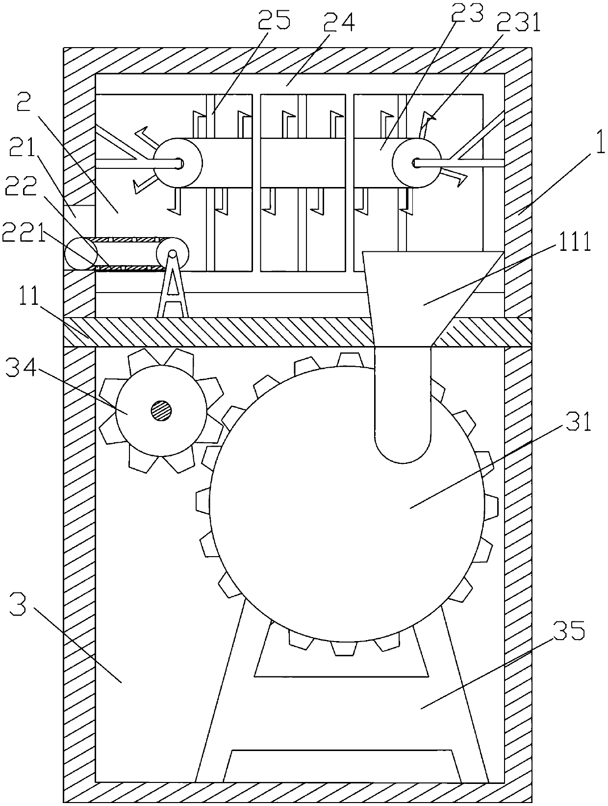
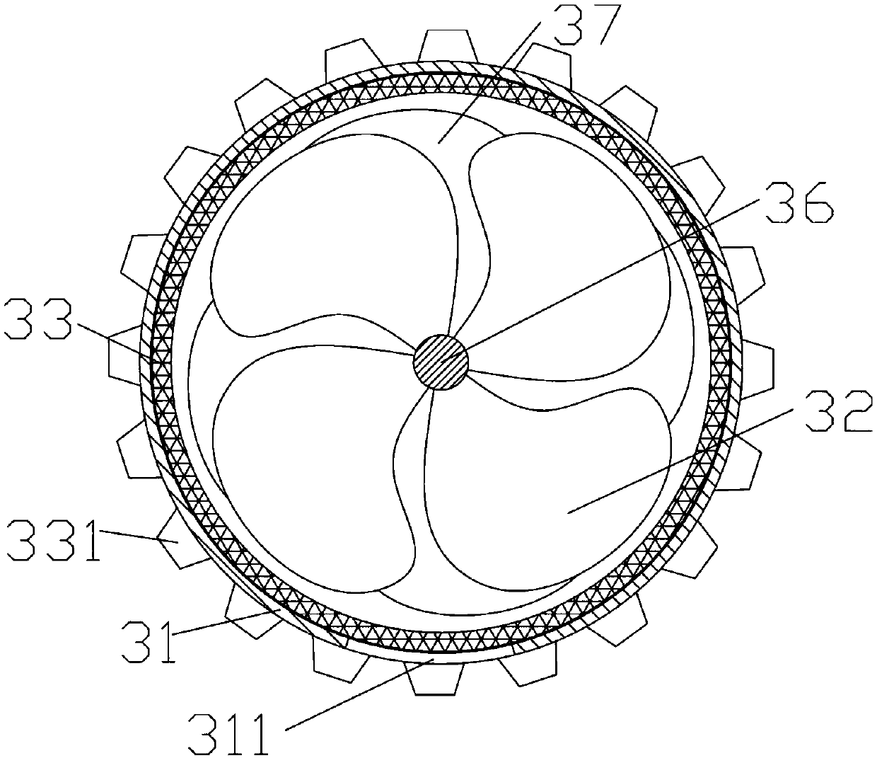
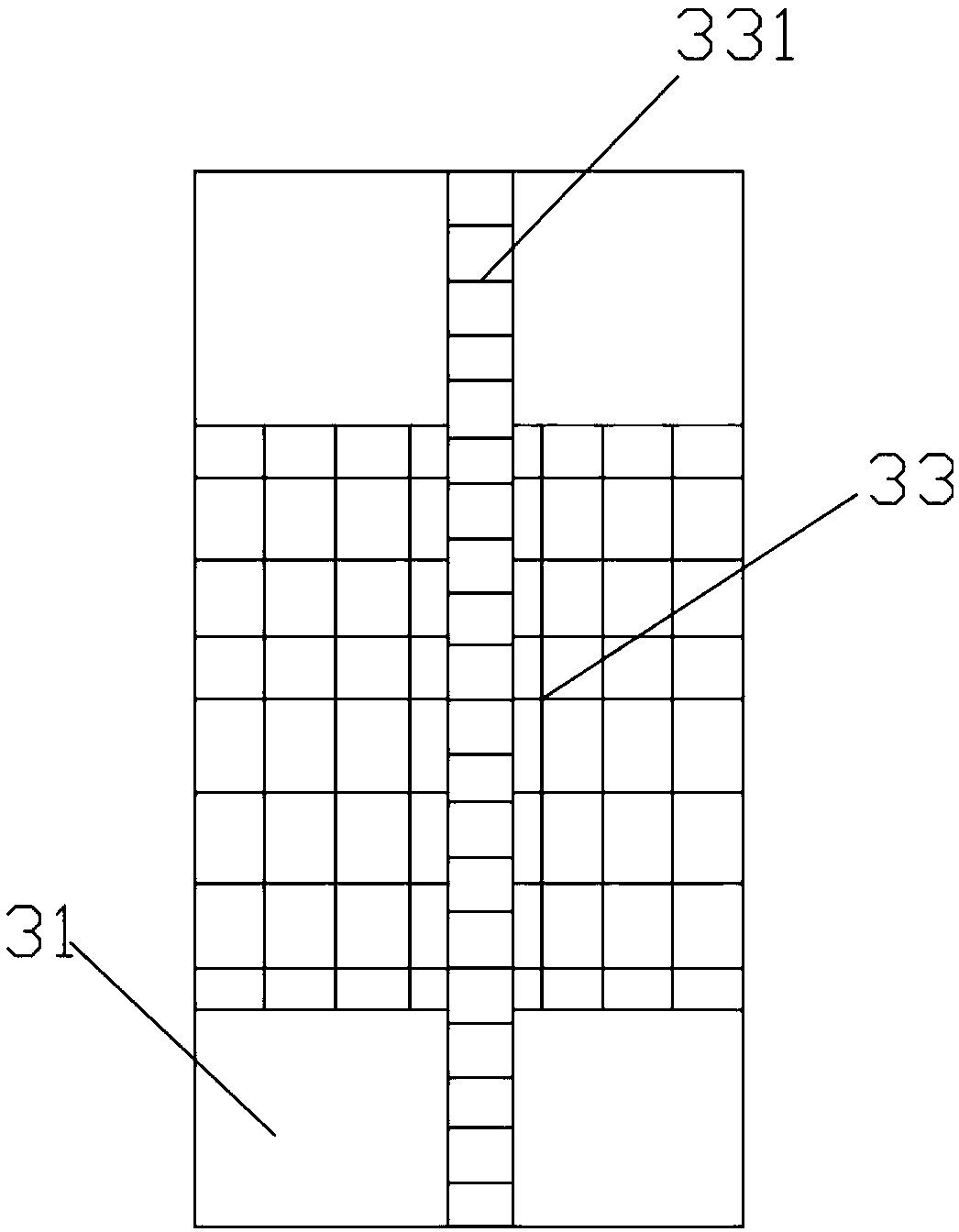
[0019] Such as Figure 1-4 As shown, a waste tire shredder includes a box body 1, and the box body 1 is provided with a partition 11, a heating chamber 2 above the partition 11, and a crushing chamber 3 below the partition 11. The heating chamber 2 is provided with a heating mechanism, and the crushing chamber 3 is provided with a crushi...


PUM


Abstract

The invention discloses a waste tire crusher. The comprises a box body, wherein a partition plate, a heating cavity arranged above the partition plate and a crushing cavity arranged below the partition plate are arranged in the box body, the heating cavity is internally provided with a heating mechanism, and the crushing cavity is internally provided with a crushing mechanism. According to the waste tire crusher, the partition plate is arranged, the box body is divided into the upper cavity and the lower cavity which are independent, and the two cavities can work independently and can also cooperate with each other for running, so that the working efficiency is improved; the heating mechanism is used for heating waste tires to a softening degree without melting, and the crushing mechanismis used for crushing and cutting the waste tires, so that the follow-up utilization of the waste tires is facilitated; and due to the adoption of the structure, the softened waste tires can enter thecrushing mechanism to be crushed in a mode of being more labor-saving and efficient, and the crushing efficiency of the waste tires is greatly improved.

Description

technical field [0001] The invention belongs to the technical field of waste tire shredding, and in particular relates to a waste tire shredder. Background technique [0002] my country is the third largest tire producer in the world, so a large number of waste tire processing equipment has appeared on the market. The waste tire primary shredder currently in use is to put the whole waste tire on the whole tire conveyor and send it to the whole tire shredder for processing. Crushing, through the repeated crushing of the cutter head, and finally the rubber block is discharged from the screen. The raw material of the rubber block is rubber material with high elasticity. The ordinary cutter head is easily broken and the cutter head is damaged, and the efficiency is not high. The rubber blocks are easy to get stuck on the mesh of the screen, and the subsequent rubber blocks will pile up on the original rubber blocks to cause blockage. Once the blockage is too much, it will cause th...

Claims


Application Information

Patent Timeline
Patent Type & Authority Patents(China)
IPC IPC(8): B29B17/04B29B17/00B29B13/10B29B13/02
CPCB29B13/02B29B13/10B29B17/00B29B17/0412B29B2017/044Y02W30/52Y02W30/62
Inventor 李颖
Owner 常州绿境环保科技有限公司
Learn More