Turbojet engine with thrust take-up means on the inter-compressor case

A compressor housing and turbojet technology, applied in the field of aviation propulsion, can solve the problems of low mechanical strength, increased weight and low mechanical strength of the compressor housing.

Active Publication Date: 2018-08-31
SAFRAN AIRCRAFT ENGINES SAS
View PDF6 Cites 1 Cited by
  • Summary
  • Abstract
  • Description
  • Claims
  • Application Information

AI Technical Summary

Problems solved by technology

This is not without consequences: the BP compressor casing has low mechanical strength, and the axial stresses corresponding to the thrust absorption on the casing can lead to deformations, as a result of which, on the one hand, the clearance of the leading blades is increased, resulting in a loss of efficiency, or On the other hand, the clearance of the front blades is reduced, creating a risk of stator / rotor contact
[0012] The low mechanical strength of the BP compressor can be compensated by using the same material to increase its thickness, which leads to an increase in weight
However, as long as the stress propagates through it, deformation can be observed with the above mentioned consequences

Method used


Image

  • Turbojet engine with thrust take-up means on the inter-compressor case
  • Turbojet engine with thrust take-up means on the inter-compressor case
  • Turbojet engine with thrust take-up means on the inter-compressor case

Examples


Embodiment Construction

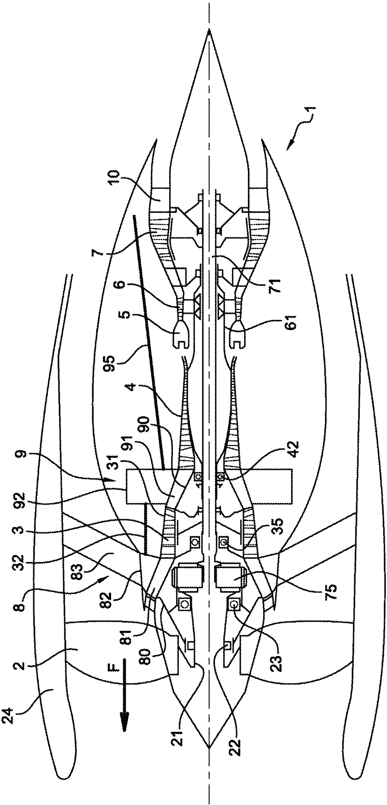
[0046] figure 1 Shown is a turbojet engine 1 with a ducted fan 2 from upstream to downstream and a gas twin formed by a first compressor 3 , a second compressor 4 , a combustion chamber 5 and two successive turbines 6 and 7 generator. The first compressor forms a low-pressure BP body together with the turbine 7 and is connected to the turbine 7 through a turbine shaft 71 . The second compressor 4 together with the turbine 6 forms a high-pressure HP body, and the second compressor is connected with the turbine 6 through a turbine shaft 61 . The fixed structural members that transfer the stress from the engine to the suspension include: the inlet housing 8 (at the inlet of the gas generator between the ducted fan 2 and the BP compressor 3 ), between the BP compressor 3 and the HP An intermediate compressor casing 9 between the compressors 4, and a discharge casing 10 downstream.

[0047] The shaft 21 of the ducted fan is rotatably mounted in two bearings 22 and 23, of which t...


PUM


Abstract

The present invention relates to a multiflow turbojet engine comprising: a. an upstream fan (2) driven by a gas generator; b. the gas generator comprising first (3) and second (4) coaxial compressors;c. an intake case (8) forming a mounting for the rotors of the fan (2) and the first compressor (3); d. an inter-compressor case (9) downstream from the intake case (8) and forming a mounting for therotor of the second compressor (4); and e. attachment means for thrust take-up control rods (95) arranged in the inter-compressor case. The turbojet engine is characterised in that it comprises a structural force shroud (32) connecting the intake case (8) to the inter-compressor case (9), the case (31) of the first compressor being floating.

Description

technical field [0001] The invention relates to the field of aeronautical propulsion. The present invention relates to the suspension of a turbojet engine onto an aircraft, and more particularly to the arrangement of the transmission or thrust absorption provided by the engine to the structure of the aircraft. Background technique [0002] The prior art includes documents US-A1-2012 / 195753, EP-A2-2 592 235, US-A1-2008 / 098717 and CA-A1-2 929 947. [0003] A multi-flow turbocharged engine of known architecture according to the prior art comprises a ducted fan and a gas generator from upstream to downstream in the direction of the air flow through the turbojet engine, by means of The fan and gas generator are rotationally driven. The gas generator consists of at least one compressor, an annular combustion chamber, at least one turbine and a combustion gas exhaust pipe. The air compressed by the ducted fan is divided into two concentric flows: a primary central flow that supp...

Claims


Application Information

Patent Timeline
Patent Type & Authority Applications(China)
IPC IPC(8): F01D25/16F01D25/24F01D25/28F02K3/06F02C7/20
CPCF01D25/162F01D25/24F01D25/246F01D25/28F02C7/20F02K3/06F05D2230/642F05D2240/90F05D2250/41Y02T50/60
Inventor 米歇尔·吉尔伯特·罗兰·布罗尼尔斯·爱德华·罗曼·博尔多尼罗曼·吉拉姆·古维列吉拉姆·帕特里斯·库比亚克阿诺·尼古拉斯·内格里娜塔莉·诺瓦克斯基
Owner SAFRAN AIRCRAFT ENGINES SAS
Why Eureka
Try Eureka