
Light and small type permanent magnetic packaging Ku waveband coaxial transition device

A light and small, ku-band technology, which is applied to the circuit components of transit-time electron tubes, transit-time electron tubes, and cathodes of transit-time electron tubes, etc., can solve the problems of low microwave efficiency and achieve high power capacity, The effect of reducing the guiding magnetic field and reducing the radial fluctuation

Active Publication Date: 2018-08-31
NAT UNIV OF DEFENSE TECH
View PDF1 Cites 17 Cited by
  • Summary
  • Abstract
  • Description
  • Claims
  • Application Information

AI Technical Summary

Problems solved by technology

[0007] From the above, it can be seen that the Ku-band coaxial transit time oscillator has the advantages of simple structure and high output efficiency, but the report of permanent magnet packaging has not yet appeared, and the microwave efficiency obtained under low guiding magnetic field is also low

Method used


Image

  • Light and small type permanent magnetic packaging Ku waveband coaxial transition device
  • Light and small type permanent magnetic packaging Ku waveband coaxial transition device
  • Light and small type permanent magnetic packaging Ku waveband coaxial transition device

Examples


Embodiment Construction

[0025]The accompanying drawings constituting a part of this application are used to provide further understanding of the present invention, and the schematic embodiments and descriptions of the present invention are used to explain the present invention, and do not constitute an improper limitation of the present invention.

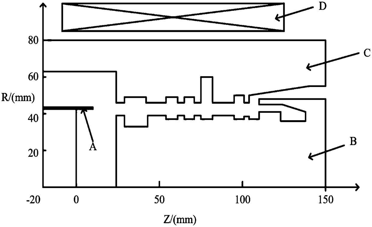
[0026] figure 1 It is a schematic structural diagram of a Ku-band coaxial transit time oscillator published in prior art 1. The structure is composed of cathode A, inner conductor B, outer conductor C and magnetic field coil D, and the whole structure is rotationally symmetrical about the central axis. Using particle simulation software, under the conditions of diode voltage 410kV, current 8kA, and guiding magnetic field 0.3T, the program obtained an output microwave power of 820MW, a microwave frequency of 14.2GHz, and a device efficiency of 25%. However, the efficiency of this device is relatively low, and it is guided by a magnetic field coil. The vol...


PUM


Abstract

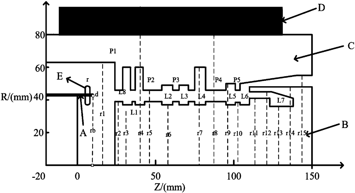
The invention relates to a light and small type permanent magnetic packaging Ku waveband coaxial transition device. The cathode A of a focusing cathode E is loaded; explosion electronic emission occurs under the condition of externally added high voltage; after electronic beams pass cascading double resonance reflection cavities, initial speed pre-modulation is acquired; speed modulation is completely converted into density modulation; high-frequency electric fields in the cavities are extracted and sufficient interactions occur between the high-frequency electric fields and clustering electronics transmitted therein; generated Ku waveband HPM is externally coupled and output through coaxial output waves; and finally, coaxial grooves in an inner conductor B absorb electronic beams of restenergy. The intensity of the generated electric fields is 0.3T, the weight of the permanent magnet is 63.5kg; and under the guidance magnetic field, effective emission and transmission of the electronic beams are achieved. By introducing the cascading double resonance reflection cavities, coupling of the electromagnetic fields in the modulation cavities to diode regions is reduced, radial fluctuation of the electronic beams is reduced and the required guidance magnetic field is reduced. The working mode of the device is TM02, so the novel device is allowed to have quite high power cavity in the Ku waveband.

Description

technical field [0001] The invention relates to a microwave source device in the technical field of high-power microwaves, in particular to a Ku-band coaxial transition device based on light and small permanent magnet packaging, and belongs to the technical field of high-power microwaves. Background technique [0002] High-power microwave usually refers to electromagnetic waves with a peak power greater than 100MW and a frequency between 1 and 300GHz. It has been widely used in many national defense and industrial fields such as directed energy weapons, radar satellites, electronic high-energy radio frequency accelerators, remote sensing and radiation measurement. [0003] The high-power microwave source is the core component for generating high-power microwave radiation. It uses the interaction between the high-current electron beam and the resonant cavity to generate high-power microwave. Transit-time oscillators use high-current electron beams to exchange energy with the ...

Claims


Application Information

Patent Timeline
Patent Type & Authority Applications(China)
IPC IPC(8): H01J25/22H01J23/04H01J23/10H01J23/20
CPCH01J23/04H01J23/10H01J23/20H01J25/22H01J2223/04H01J2223/10H01J2223/20H01J2225/22
Inventor 令钧溥陈浩嘉钱宝良贺军涛宋莉莉
Owner NAT UNIV OF DEFENSE TECH
Learn More