High-voltage interlocking loop of electric automobile and open circuit detection method
A high-voltage interlocking circuit, electric vehicle technology, applied in the direction of measuring electricity, measuring devices, measuring electrical variables, etc., can solve problems such as inability to accurately locate high-voltage connector faults
- Summary
- Abstract
- Description
- Claims
- Application Information
AI Technical Summary
Problems solved by technology
Method used
Image
Examples
Embodiment 1
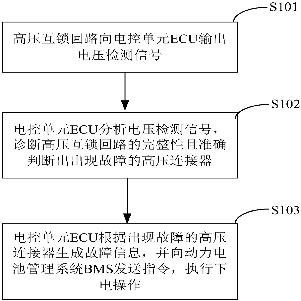
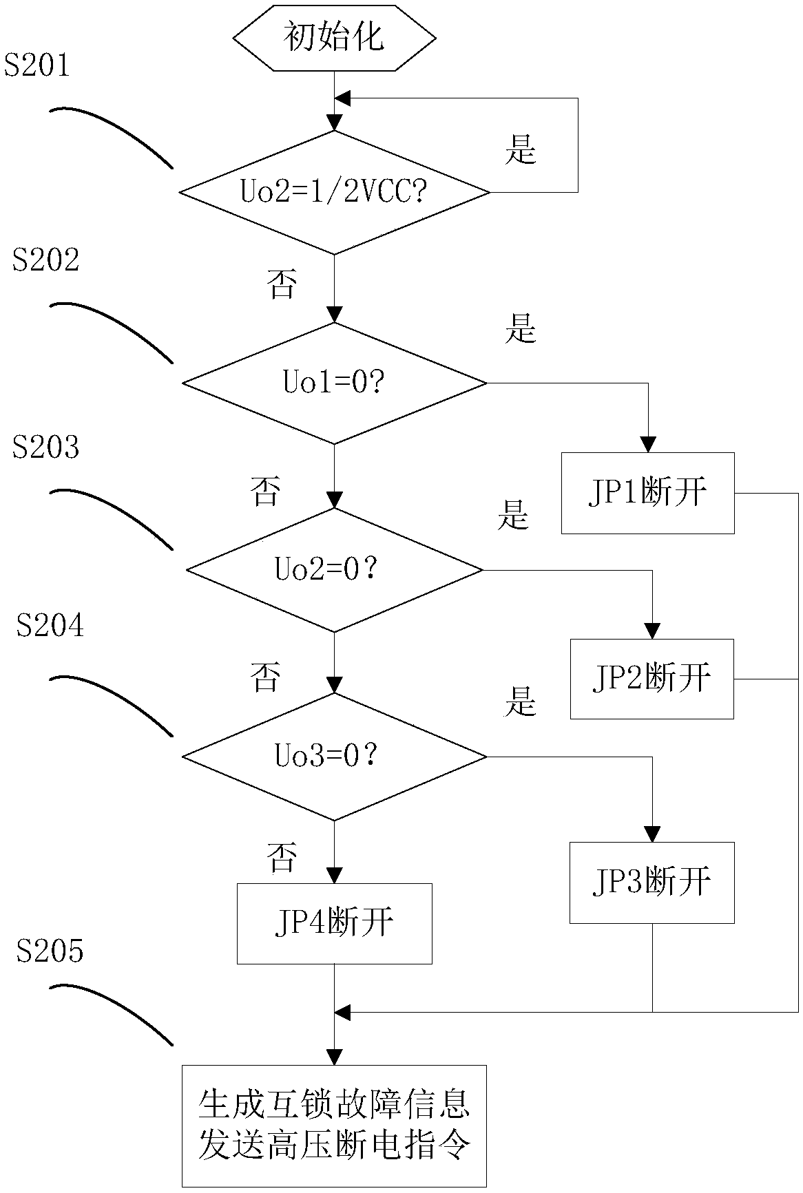
[0038]A high-voltage interlock circuit of an electric vehicle, the high-voltage interlock circuit is a low-voltage electrical connection circuit independent of the high-voltage circuit of the electric vehicle, the high-voltage interlock circuit includes an output voltage detection circuit, an output voltage circuit electrically connected to the output voltage detection circuit The voltage conditioning circuit and the electronic control unit ECU electrically connected to the output voltage conditioning circuit; one end of the output voltage detection circuit is electrically connected to the low-voltage power supply Vcc, and the other end is grounded. The output voltage detection circuit includes multiple pairs of bridges and resistors connected in series, and the bridge It is integrated with the corresponding high-voltage connector and the bridge is disconnected before the high-voltage connector when it is disconnected. The bridge can be generally understood as a wire. When the b...
Embodiment 2
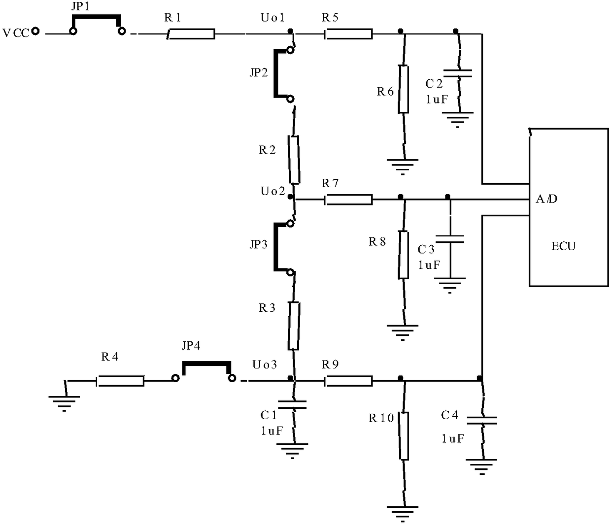
[0045] For ease of description, in combination with the detection method given in the first embodiment above, figure 2 The high-voltage interlock circuit provided by Embodiment 2 of the present invention is given.
[0046] The output voltage detection circuit includes a first detection unit, a second detection unit, a third detection unit and a fourth detection unit connected in series; the first detection unit includes a first bridge JP1, a first resistor R1 connected to the first bridge JP1 The second detection unit includes a second bridge JP2 connected to the first resistor R1, and a second resistor R2 connected to the second bridge JP2; the third detection unit includes a third bridge JP3 connected to the second resistor R2, A third resistor R3 connected to the third bridge JP3; the fourth detection unit includes a fourth bridge JP4 connected to the third resistor R3, and a fourth resistor R4 connected to the fourth bridge JP4. The remaining end of the first bridge JP1 ...
PUM
 Abstract
Description
Claims
Application Information
 - R&D
- Intellectual Property
- Life Sciences
- Materials
- Tech Scout
- Unparalleled Data Quality
- Higher Quality Content
- 60% Fewer Hallucinations
Browse by: Latest US Patents, China's latest patents, Technical Efficacy Thesaurus, Application Domain, Technology Topic, Popular Technical Reports.
© 2025 PatSnap. All rights reserved.Legal|Privacy policy|Modern Slavery Act Transparency Statement|Sitemap|About US| Contact US: help@patsnap.com


