
Power supply ripple testing device

A test device and power ripple technology, applied in the field of power ripple test devices, can solve the problems of consuming human resources, uneven strength, complicated operation, etc., and achieve the effects of reducing wear and tear, reducing maintenance costs, and stable and accurate power supply

Pending Publication Date: 2022-05-13
INSPUR SUZHOU INTELLIGENT TECH CO LTD
View PDF0 Cites 0 Cited by
  • Summary
  • Abstract
  • Description
  • Claims
  • Application Information

AI Technical Summary

Problems solved by technology

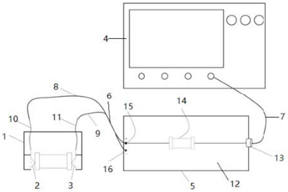
[0004] Therefore, the technical problem to be solved by the present invention is to overcome the defects in the prior art that the operation consumes human resources when testing the power supply ripple and noise, and the test error is caused by uneven force, the operation is complicated, and the efficiency is low, thereby providing a Power Ripple Test Set

Method used


Image

  • Power supply ripple testing device

Examples


Embodiment Construction

[0030] The technical solutions of the present invention will be clearly and completely described below in conjunction with the accompanying drawings. Apparently, the described embodiments are some of the embodiments of the present invention, but not all of them. Based on the embodiments of the present invention, all other embodiments obtained by persons of ordinary skill in the art without making creative efforts belong to the protection scope of the present invention.

[0031] In the description of the present invention, it should be noted that the terms "center", "upper", "lower", "left", "right", "vertical", "horizontal", "inner", "outer" etc. The indicated orientation or positional relationship is based on the orientation or positional relationship shown in the drawings, and is only for the convenience of describing the present invention and simplifying the description, rather than indicating or implying that the referred device or element must have a specific orientation, ...


PUM


Abstract

The invention provides a power supply ripple test device. The power supply ripple test device comprises a test shell, a display module and a blocking module, the test shell covers the outside of the to-be-tested module, a positive electrode contact end and a negative electrode contact end are arranged in the test shell, the positive electrode contact end is connected with the positive electrode of the to-be-tested module, and the negative electrode contact end is connected with the negative electrode of the to-be-tested module; a display module; and one end of the blocking module is connected with the positive electrode contact end and the negative electrode contact end through a first connecting line, and the other end is connected with the display module through a second connecting line. When the power supply ripple and noise are tested, only the positive electrode contact end and the negative electrode contact end of the test shell need to be clamped at the two ends of the power supply to be tested, a worker does not need to hold the probe all the time, convenience is improved, and force is uniform in the testing process. And moreover, the ripple and noise of the power supply are tested in a clamping manner, repeated welding is not needed, a large amount of welding time is saved, and the operation is simple and efficient.

Description

technical field [0001] The invention relates to the technical field of power supply testing, in particular to a power supply ripple testing device. Background technique [0002] With the rapid development of science and technology, the power consumption of electronic products is getting smaller and smaller, the power supply voltage is getting lower and lower, the accuracy of the output voltage of the power supply is getting higher and higher, and the tolerance of electronic products to ripple noise is getting smaller and smaller. Most electronic products need to consider the signal integrity of the DC power supply when designing, and power supply ripple noise, as one of the important indicators of power integrity, has become a must-test item in the product testing process. [0003] There are about three popular power supply ripple and noise test methods at present, and the test methods adopted by each company are different. The first test method is to use the standard activ...

Claims


Application Information

Patent Timeline
Patent Type & Authority Applications(China)
IPC IPC(8): G01R31/40
CPCG01R31/40
Inventor 李强
Owner INSPUR SUZHOU INTELLIGENT TECH CO LTD
Learn More