polisher

A polishing machine and workpiece technology, applied in the field of polishing machines, can solve the problems of difficult to guarantee polishing effect and quality, hidden dangers of health and safety, low polishing efficiency, etc., to improve polishing efficiency and safety, low manufacturing cost, and helpful effect on equipment cooling

Active Publication Date: 2022-02-08
福建万晟机械有限公司
View PDF9 Cites 0 Cited by
  • Summary
  • Abstract
  • Description
  • Claims
  • Application Information

AI Technical Summary

Problems solved by technology

[0002] Most of the existing polishing operations use grinding wheels to polish the surface of the workpiece, which generally has the following disadvantages: 1. For the polishing operations on regular planes, the grinding wheels can still be completed, while for the polishing operations on irregular planes, many of them are hand-held small polishing machines or Sandpaper is used for polishing, and the smoothness and flatness of the surface of the workpiece after manual polishing are completely determined by the operator, and the polishing effect and quality are difficult to guarantee; 2. Some objects with cavities or hollows have no Enough space is left for polishing equipment and polishing personnel to operate; 3. Most of the existing polishing equipment is for polishing a single workpiece, which is inefficient and time-consuming; 4. During the polishing operation, the polishing wear of the workpiece will generate a large amount dust particles, and the operators are not well isolated from the workpiece and equipment, so there are great health and safety hazards

Method used


Image

  • polisher
  • polisher
  • polisher

Examples


Embodiment 1

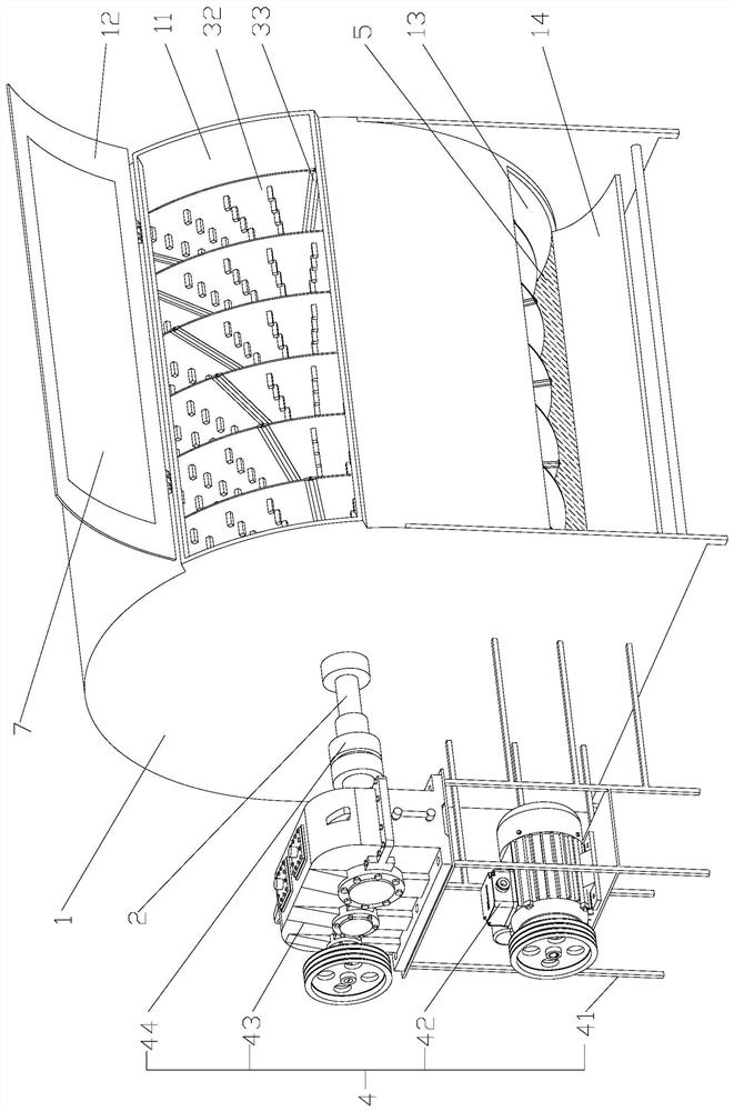
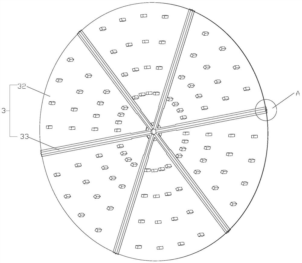
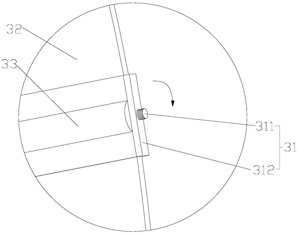
[0041] Such as Figure 1-7As shown, the polishing machine of the present invention includes a cylinder body 1, a rotating shaft 2 arranged laterally in the cylinder body 1 and rotatably connected to the cylinder body 1, and more than one workpiece arranged in sequence along the axial direction of the rotating shaft 2 and fixedly connected to the rotating shaft 2 The mounting plate 3, the driving device 4 provided on the outside of the cylinder 1 and connected to the rotating shaft 2 for driving the rotation of the rotating shaft 2, and the polishing material 5 filled in the cylinder 1 for assisting in polishing the workpiece 6 to be polished, the workpiece The mounting plate 3 is provided with more than one workpiece positioning part 321 for installing and fixing the workpiece 6 to be polished, and the cylinder body 1 is provided with a workpiece inlet 11 and a first material door 12 for opening and closing the workpiece inlet 11; Each workpiece mounting plate 3 includes more ...

Embodiment 2

[0045] Such as Figure 8 As shown, the difference between Embodiment 2 and Embodiment 1 is that the polishing machine includes a barrel 1, and the inner cavity of the barrel 1 is provided with two horizontally arranged and parallel rotating shafts 2, and each rotating shaft 2 is rotationally connected with the barrel 1; Each rotating shaft 2 is fixedly connected with more than one workpiece mounting plate 3 which is sequentially arranged along the axial direction of the rotating shaft 2; the cylinder body 1 is provided with a driving device 4 for driving each rotating shaft 2 to rotate, and the rotation directions of the two rotating shafts 2 are opposite, and The distance between the two rotating shafts 2 is greater than the sum of the radii of the workpiece mounting discs 3 installed on the two rotating shafts 2; the cylinder body 1 is filled with polishing material 5 for assisting in polishing the workpiece 6 to be polished, and the upper surface after the polishing material...


PUM


Abstract

The invention relates to the field of workpiece processing, in particular to a polishing machine, which includes a cylinder body, a rotating shaft, a workpiece mounting plate, a driving device and polishing materials, a workpiece positioning component is arranged on the workpiece mounting plate, and a first material door is provided on the cylinder body; The invention provides a polishing machine, which can not only isolate the polishing operation of the workpiece from the operator to prevent dust pollution, but also can adapt to a variety of workpieces of different shapes and sizes, and can polish multiple workpieces at the same time. Expand the polishing range, and significantly improve the polishing efficiency.

Description

technical field [0001] The invention relates to the field of workpiece processing, in particular to a polishing machine. Background technique [0002] Most of the existing polishing operations use grinding wheels to polish the surface of the workpiece, which generally has the following disadvantages: 1. For the polishing operations on regular planes, the grinding wheels can still be completed, while for the polishing operations on irregular planes, many of them are hand-held small polishing machines or Sandpaper is used for polishing, and the smoothness and flatness of the surface of the workpiece after manual polishing are completely determined by the operator, and the polishing effect and quality are difficult to guarantee; 2. Some objects with cavities or hollows have no Enough space is left for polishing equipment and polishing personnel to operate; 3. Most of the existing polishing equipment is for polishing a single workpiece, which is inefficient and time-consuming; 4...

Claims


Application Information

Patent Timeline
Patent Type & Authority Patents(China)
IPC IPC(8): B24B31/10B24B31/12B24B41/06B24B47/12
CPCB24B31/10B24B31/12B24B41/06B24B47/12
Inventor 蔡庆旺蔡晟陈宝儿
Owner 福建万晟机械有限公司
Why Eureka
Try Eureka