
Side surface polishing device for glass light guide plate

A glass light guide plate and polishing device technology, applied in grinding/polishing safety devices, grinding/polishing equipment, machine tools suitable for grinding workpiece planes, etc., can solve scratches on the surface of the light guide plate, insufficient polishing brightness, and waste Labor and other issues, to avoid polishing scratches, improve polishing fineness, and simple structure

Active Publication Date: 2018-08-31
DONGGUAN YINTAIFENG OPTICAL TECH CO LTD
View PDF7 Cites 2 Cited by
  • Summary
  • Abstract
  • Description
  • Claims
  • Application Information

AI Technical Summary

Problems solved by technology

Due to the mobile grinding method of the mechanical arm, when the polishing wheel is displaced, it is easy to cause scratches on the surface of the light guide plate, and the polishing brightness is insufficient
During the polishing process, the light guide plate needs to be fixed, flipped, picked and placed continuously, and only one side of the light guide plate can be polished each time, the production efficiency is very low, and a lot of labor is wasted

Method used


Image

  • Side surface polishing device for glass light guide plate
  • Side surface polishing device for glass light guide plate

Examples


Embodiment Construction

[0016] In order to further understand the features, technical means, and specific objectives and functions achieved by the present invention, the present invention will be further described in detail below in conjunction with the accompanying drawings and specific embodiments.

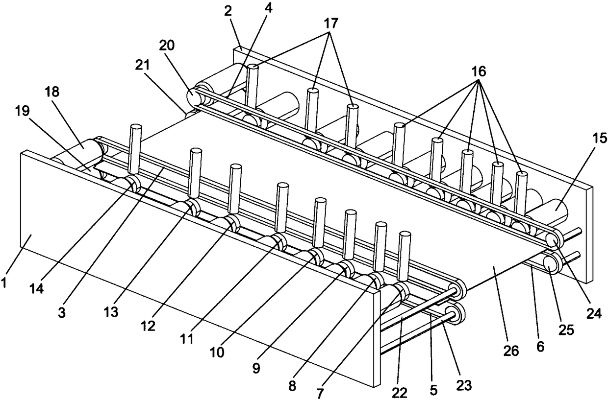
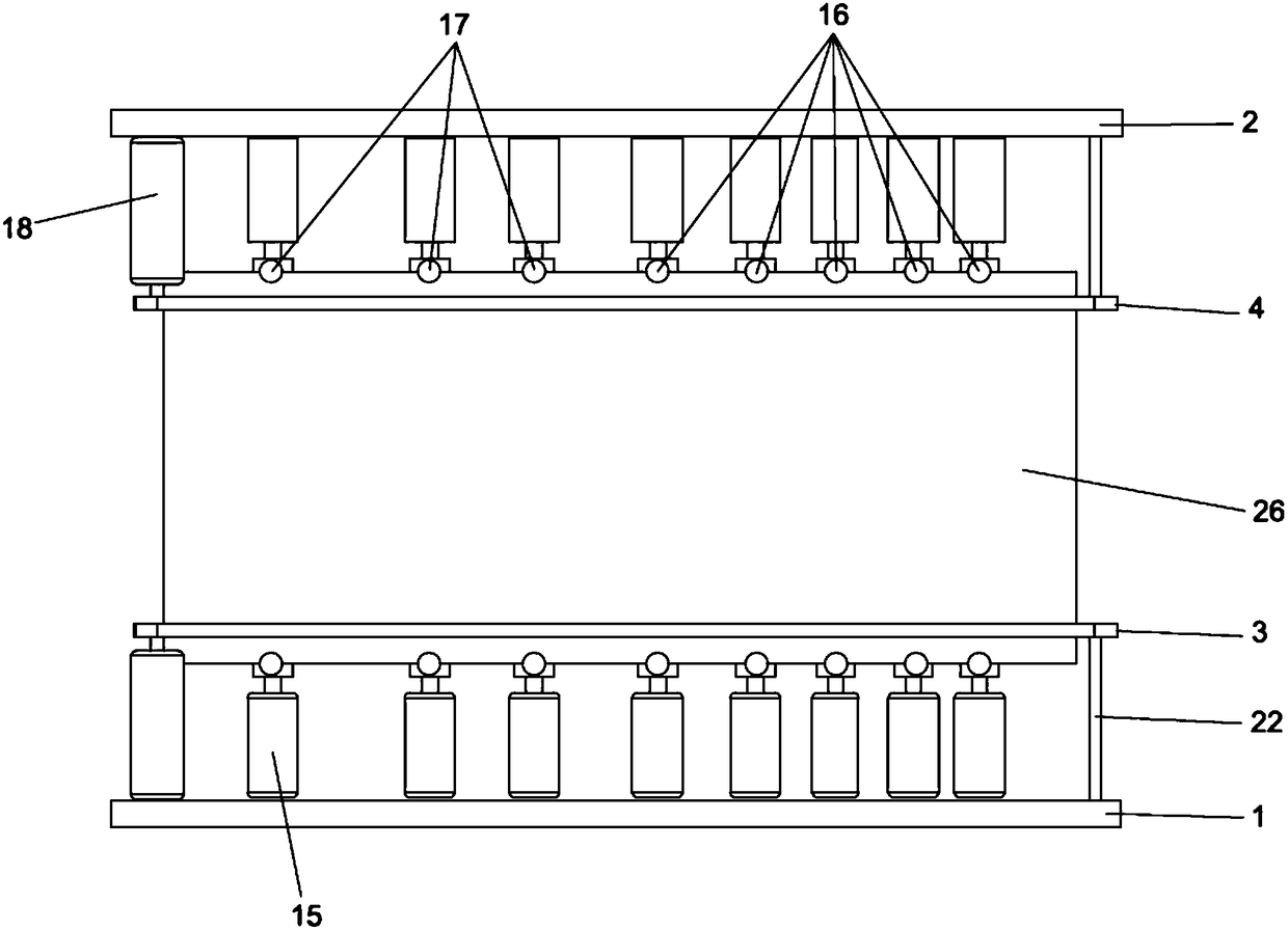
[0017] refer to Figure 1 to Figure 2 .

[0018] The embodiment of the present invention discloses a side polishing device for a glass light guide plate, which includes an oppositely arranged backing board A1 and a backing board B2, and an upper conveyor belt A3 and an upper conveyor belt B4 are arranged oppositely between the backing board A1 and the backing board B2. The lower conveyor belt A5 and the lower conveyor belt B6, the upper conveyor belt A3 is located above the lower conveyor belt A5 and arranged side by side with the lower conveyor belt A5, the upper conveyor belt B4 is located above the lower conveyor belt B6 and arranged side by side with the lower conveyor belt B6, and between the uppe...


PUM


Abstract

The invention provides a side surface polishing device for a glass light guide plate. The side surface polishing device comprises an upper conveyor belt A, an upper conveyor belt B, a lower conveyor belt A and a lower conveyor belt B, wherein the upper conveyor belt A and the upper conveyor belt B are arranged relatively, and the lower conveyor belt A and the lower conveyor belt B are arranged relatively. First polishing wheels, second polishing wheels, third polishing wheels, fourth polishing wheels, fifth polishing wheels, sixth polishing wheels, seventh polishing wheels and eighth polishingwheels which are driven by motors A to rotate are sequentially arranged on one side between the upper conveyor belt A and the lower conveyor belt A and one side between the upper conveyor belt B andthe lower conveyor belt B. Liquid transfer tubes A used for inputting clear water are arranged on one sides of the first polishing wheels, the second polishing wheels, the third polishing wheels, thefourth polishing wheels and the fifth polishing wheels, and liquid transfer tubes B used for inputting polishing liquid are arranged on one sides of the sixth polishing wheels, the seventh polishing wheels and the eighth polishing wheels. The polishing process is carried out during the transmission of the light guide plate to improve the polishing efficiency and the degree of finish of the polished surface.

Description

technical field [0001] The invention relates to the technical field of glass light guide plate processing, and specifically discloses a glass light guide plate side polishing device. Background technique [0002] During the processing of the glass light guide plate, the light guide plate needs to be cut. The side of the cut light guide plate is rough and needs to be polished to improve the smoothness of the side of the light guide plate and reduce the loss of light transmission. The polishing treatment of the side of the glass light guide plate is very important, which affects the quality of the light guide plate. [0003] At present, when polishing the side of the glass light guide plate, the light guide plate is generally fixed on a jig first, and then the side of the light guide plate is mobilely ground by a rotating polishing wheel driven by a mechanical arm. Due to the mobile grinding method of the mechanical arm, when the polishing wheel shifts, it is easy to cause sc...

Claims


Application Information

Patent Timeline
Patent Type & Authority Applications(China)
IPC IPC(8): B24B7/26B24B27/00B24B41/00B24B55/06B24B57/02
CPCB24B7/265B24B27/0076B24B41/005B24B55/06B24B57/02Y02P40/57
Inventor 李飞
Owner DONGGUAN YINTAIFENG OPTICAL TECH CO LTD
Learn More