Casing gas recovery device

A recovery device and casing gas technology, applied in wellbore/well components, piston pumps, production fluids, etc., can solve problems such as difficult utilization and recovery of casing gas, potential safety hazards in oil fields, and difficult maintenance, etc. Casing gas recovery problem, effective casing gas recovery, and the effect of solving air lock phenomenon

Active Publication Date: 2020-09-29
李青坤
View PDF6 Cites 0 Cited by
  • Summary
  • Abstract
  • Description
  • Claims
  • Application Information

AI Technical Summary

Problems solved by technology

[0002] The production wellhead is composed of tubing and casing. When crude oil is extracted in the oil field, the crude oil is pumped out of the tubing through the pumping unit. When entering the middle and late stages of oilfield development, low output, low casing gas pressure, and in-process production often occur. Casing gas is difficult to be utilized and recovered. Part of the natural gas accumulates in the annular space of the oil casing, resulting in a decrease in oil well pressure and production capacity. At the same time, it also wastes precious and non-renewable clean resources, forming a vicious circle, and it is also a hidden danger to the safety of oil areas.
[0003] In order to solve the above problems, the currently mature and applied products are mostly constant pressure release valves, which are low in cost and simple in structure, but the premise is that the casing gas must be held for a long time to reach a certain pressure before it can enter the oil and gas production trunk line. The long-term pressure of the casing gas will directly affect the production capacity of the oil well; the other is to install a cylinder on the support of the pumping unit, and the cylinder rod is fixed on the beam of the pumping unit to connect with each other to realize reciprocating movement. The disadvantage is The installation cost is high, the maintenance is difficult, and sometimes there will be a fatal flaw that the pumping unit will be turned over when the cylinder is stopped, and the above methods need to be shut down and removed during maintenance.

Method used


Image

  • Casing gas recovery device

Examples


Embodiment Construction

[0016] Below in conjunction with specific embodiment, further illustrate the present invention. It should be understood that these examples are only used to illustrate the present invention and are not intended to limit the scope of the present invention. In addition, it should be understood that after reading the content taught by the present invention, those skilled in the art may make various changes or modifications to the present invention, and these equivalent forms also fall within the scope defined in the present application.

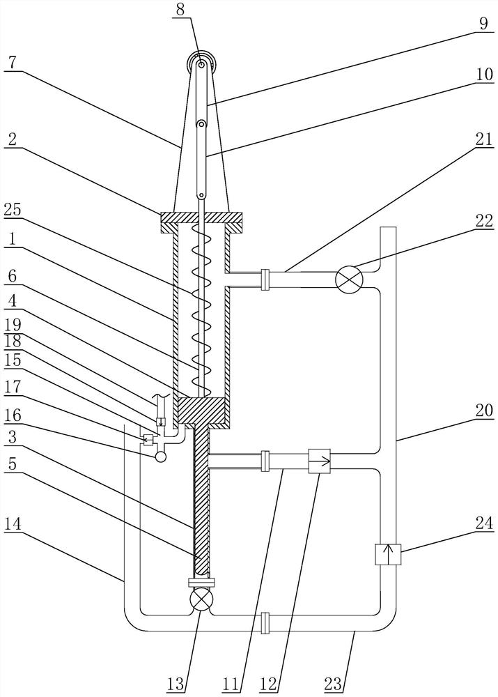
[0017] The casing gas recovery device described in the present invention includes a gas compression cylinder 1, the top of the gas compression cylinder 1 is provided with a sealing flange 2, and the middle of the bottom end of the gas compression cylinder 1 is provided with a gas compression cylinder 1. The liquid discharge cylinder 3 connected to the cylinder 1, the inner diameter of the liquid discharge cylinder 3 is smaller than the inner dia...


PUM


Abstract

The invention discloses a casing gas recovery device, and relates to the technical field of oil recovery. The device comprises a gas compression cylinder body, a sealing flange is arranged on the topof the gas compression cylinder body, a liquid discharging cylinder body communicated with the gas compression cylinder body is arranged in the middle of the bottom end of the gas compression cylinderbody, an upper piston is arranged in the compression cylinder body, a lower piston is arranged in the liquid discharging cylinder body, a liquid discharging pipe is arranged on the upper portion of the outer wall of the liquid discharging cylinder body, a liquid discharging one-way valve is arranged on the liquid discharging pipe, a liquid inlet valve is arranged at the bottom of the liquid discharging cylinder body, a liquid inlet pipeline is arranged at the end, away from the liquid discharging cylinder body, of the liquid inlet valve, a four-way valve is arranged at the bottom of the gas compression cylinder body, and the first interface of the four-way valve is communicated with the gas compression cylinder body. The casing gas recovery device has the advantages that the problem of oil well casing gas recovery can be effectively solved without additional external powering energy, the recovery of the casing gas is effectively achieved to solve the phenomenon of gas lock, and therefore oil well yield is improved.

Description

technical field [0001] The invention relates to the technical field of oil recovery, in particular to a casing gas recovery device. Background technique [0002] The production wellhead is composed of tubing and casing. When crude oil is extracted in the oil field, the crude oil is pumped out of the tubing through the pumping unit. When entering the middle and late stages of oilfield development, low output, low casing gas pressure, and in-process production often occur. Casing gas is difficult to be utilized and recovered. Part of the natural gas accumulates in the annular space of the oil casing, resulting in a decrease in oil well pressure and production capacity. At the same time, precious and non-renewable clean resources are wasted, forming a vicious circle, and it is also a hidden danger to the safety of oil fields. [0003] In order to solve the above problems, the currently mature and applied products are mostly constant pressure release valves, which are low in co...

Claims


Application Information

Patent Timeline
Patent Type & Authority Patents(China)
IPC IPC(8): E21B43/00F04B37/12F04B35/00
CPCE21B43/00F04B35/00F04B37/12
Inventor 李青坤
Owner 李青坤
Why Eureka
Try Eureka