
Construction method for concrete structure with fabricated masonry filler walls

A technology of concrete structure and construction method, applied in the direction of walls, building components, building structures, etc., can solve the problems of formwork removal difficulty, filling wall disturbance, high labor cost, etc., to ensure integrity and connection reliability, construction The process is simple and convenient, and the effect of high-quality wall masonry

Inactive Publication Date: 2018-08-28
黄靓 +1
View PDF8 Cites 0 Cited by
  • Summary
  • Abstract
  • Description
  • Claims
  • Application Information

AI Technical Summary

Problems solved by technology

[0002] In recent years, with the continuous advancement of construction industrialization and the rapid development of prefabricated buildings, coupled with the traditional use of artificial masonry infill walls in the construction process, there are high labor costs, high labor intensity, long time-consuming, complex construction technology and poor construction quality. The construction cost is not easy to control and other shortcomings, the development of prefabricated infill walls is imminent. From the current development and application of prefabricated infill walls, prefabricated infill walls have low bearing capacity and a certain gap between the top of the wall and the bottom of the beam. If concrete is poured directly on the top beam formwork of the prefabricated infill wall, the prefabricated infill wall may be damaged due to insufficient bearing capacity. The infill wall is disturbed and even damaged by out-of-plane forces. More importantly, it is difficult to remove the formwork directly supported on the top of the prefabricated infill wall.

Method used


Image

  • Construction method for concrete structure with fabricated masonry filler walls
  • Construction method for concrete structure with fabricated masonry filler walls
  • Construction method for concrete structure with fabricated masonry filler walls

Examples


Embodiment 1

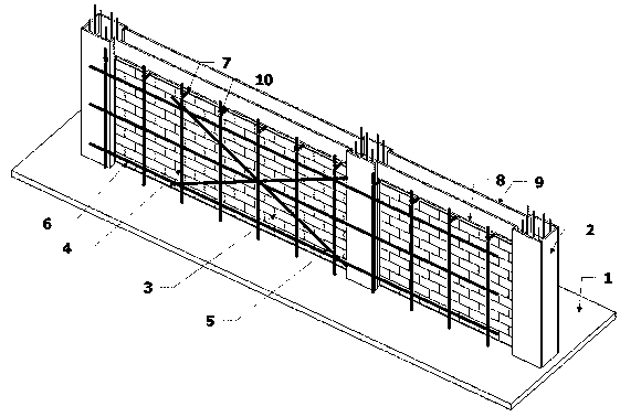
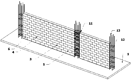
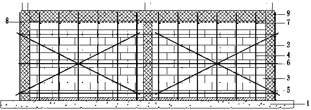
[0026] a. Confirm that the prefabricated infill wall (3) is connected and fixed with the floor (1), column or shear wall (2);

[0027] b. Upright poles (4) are supported on both sides of the prefabricated filling wall (3), and the poles (4) on the same side are fixed with oblique poles (5) and longitudinal horizontal poles (6);

[0028] c. Determine the elevation to deduct the thickness of the bottom formwork (8) of the beam formwork on the basis of the elevation of the bottom of the beam, and mark it on the pole (4);

[0029] d. Install the horizontal horizontal rod (7) at the position marked on the vertical rod, and use the connecting fastener (10) to connect and fix the horizontal horizontal rod (7) with the vertical rods on both sides of the prefabricated wall (3);

[0030] e. Install the beam formwork bottom formwork (8) and the beam formwork side formwork (9) on the horizontal bar (7), and pour the beam concrete after the beam formwork installation is completed;

[0031...


PUM


Abstract

The invention discloses a construction method for a concrete structure with fabricated masonry filler walls. The construction method comprises the specific processes that gaskets are placed on a floor(1) and mortar is laid on the floor (1), then the fabricated masonry filler walls (3) are lifted, and after the walls are lifted, the fabricated masonry filler walls (3) and frame columns or shear walls (2) are connected and fixed; then vertical rods (4) are erected on the two sides of the fabricated masonry filler walls (3), and the vertical rods (4) are fixedly connected with diagonal web members(5) and longitudinal horizontal rods (6) by connecting fasteners (10); transverse horizontal rods (7) are arranged at the bottoms of beam formwork bottom forms (8) above the fabricated masonry filler walls (3), and the transverse horizontal rods (7) and the vertical rods (4) are fixed by the connecting fasteners (10); and then the beam formwork bottom forms (8) and beam formwork side forms (9) are erected on the transverse horizontal rods (7), reinforced concrete beams are poured, and after concrete is maintained to the specified strength, formworks are removed according to the regulations.

Description

technical field [0001] The invention belongs to the technical field of construction engineering, and relates to the installation of an upper beam formwork on a prefabricated masonry filling wall, that is, a construction method for a concrete structure with a prefabricated masonry filling wall. Background technique [0002] In recent years, with the continuous advancement of construction industrialization and the rapid development of prefabricated buildings, coupled with the traditional use of artificial masonry infill walls in the construction process, there are high labor costs, high labor intensity, long time-consuming, complex construction technology and poor construction quality. The construction cost is not easy to control and other shortcomings, the development of prefabricated infill walls is imminent. From the current development and application of prefabricated infill walls, prefabricated infill walls have low bearing capacity and a certain gap between the top of the...

Claims


Application Information

Patent Timeline
IPC IPC(8): E04B2/68
Inventor 黄靓包堂堂
Owner 黄靓
Learn More